
Welcome to Day 3 of Stripping my Mazda MX-5. This post is an overview of what we did and the approach we took with stripping the vehicle. It is not intended to be a step-by-step guide of how to go about it. There are already plenty of good resources which provide this detail as I covered in a previous post.
What I do cover here is some of the things to watch out for and areas where the approach we took deviated from the YouTube videos and why. I have included a couple of videos below to give you an impression of how it went on Day 3. Hopefully, this is a more custom guide for MK Indy RX-5 builders. So here goes.
Work Completed on Day 3
Today was building on the success of Day 2 and finally separating the shell from the roller skate. Here is the order in that we approached Day 3:
Drain Fuel
Before we did anything with fuel we confiscated Dave’s cigarettes and lighter… Safety first, be very careful when dealing with fuel, and take all the correct precautions. We all wore overalls, gloves, and glasses and had plenty of rags and sand for any spillages.
So the first thing we did was empty the fuel tank. Unfortunately, the MOT ran out before I really had a chance to run down the fuel in the tank. The gauge was showing half full so roughly 25l remained in the tank. We decided the best approach was to try and siphon as much out of the tank as we could. Now, the tank has an anti-siphon feature in the neck so we undid the filler pipe from inside the boot and went directly into the tank from there.
By using a long pipe and a large syringe to get the flow going we managed to siphon most of the fuel out of the tank into a large 25l container. This was then transferred to my Mercedes fuel tank. At this point, we left the fuel sender/ gauge in place in the tank to keep it sealed. To try and drain the last dregs of the fuel we then cut the fuel line as it entered the fuel filter under the car, hoping this would drain the remaining fuel. This didn’t really work, as on reflection the fuel pump is in the sender unit which pumps the fuel out of the top of the tank, so all that we managed to drain out the bottom was the fuel left in the fuel lines. So a pointless exercise.
So, if I were doing this again I would temporarily remove the fuel sender/ gauge and use the large syringe we had to empty the remainder of the tank from the top as there were a few litres left in the bottom.
Engine Fuel Connection
Once the tank was drained we then set about disconnecting the fuel lines in the engine bay. We went bold with our approach and cut the plastic line as it comes up from the transmission tunnel. We then used an 8mm bolt to screw into the cut end to stop and small drips from fuel left in the line. This worked surprisingly well!
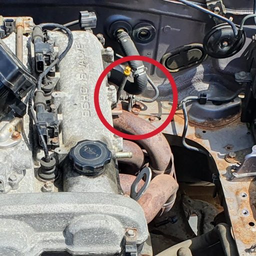
Clutch Hydraulics
We then disconnected the clutch hydraulics just to the right at the rear of the engine. As shown below circled in red. We then just strapped the flexible pipe to the engine out of the way.
Hydraulic Pipes
We then removed the hydraulic pipes for the brakes and clutch from the engine bay. This was to get them out of the way ready to scrap the shell. This is not really needed to separate the shell but we did it for good measure at this stage.
Rear Brake Disconnect
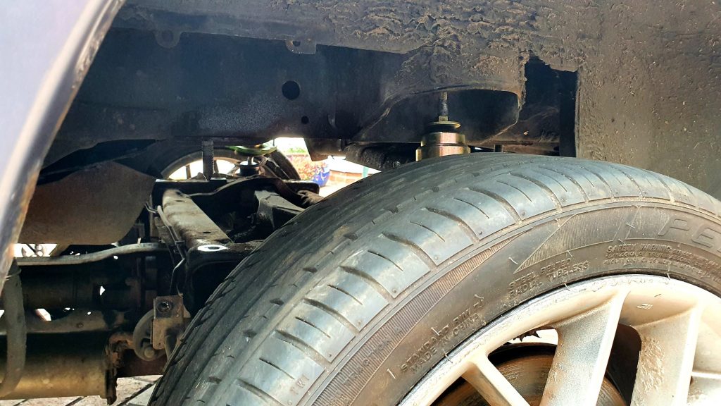
We then disconnected the rear brakes from the shell. This is actually quite straightforward as there is only one point where the brake pipes go from shell to sub-frame. This point is at the rear righthand wheel as the pipeline goes to a T-connector on the sub-frame. You simply undo it on the input and that is enough for separating the shell.
Exhaust
The exhaust does not need removing to separate the shell. This is where we deviate from the YouTube videos that we watched in preparation. In those videos, they remove the exhaust before separation. There is no point and it is much easier to remove it after you have separated the shell.
The only thing you have to do is remove both the runner exhaust hangers from the rear near the silencer. The exhaust rests nicely on the sub-frame underneath for support.
Lamda Sensors
There is 1x lambda sensor in front of the Catalytic Converter which is connected to the roller skate only, so can be left in place. The 2nd lambda sensor is just behind the Catalytic Converter which needs disconnecting from the shell and just wrapping up out the way.
Anti-roll Bar
Dave then removed the front anti-roll bar from the main brackets on the shell. The castle nuts on the ball joints were too rusted to easily get them off so it was separated at the shell fixing either side and just left to hang down out of the way.
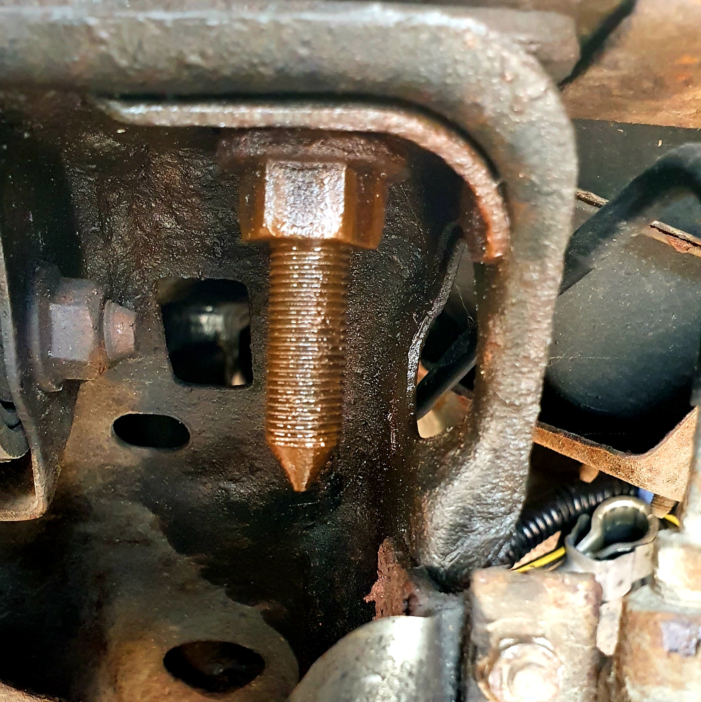
Shell Fixings
There are 12x fixings holding the shell to the sub-frames. 3 on each corner near the suspension. The image below shows the location of the rear fixings. The blue one in the centre is a bolt and easy to remove. The red ones are nuts as the thread is used to help locate the shell to the sub-frame on the production line.
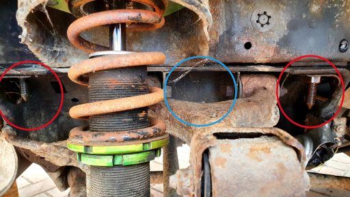
This is where you have the problem. The thread is so long that even a deep socket is not deep enough to get to the nut. So the only way to undo them is with a spanner but you can’t get the correct torque with a normal length spanner.
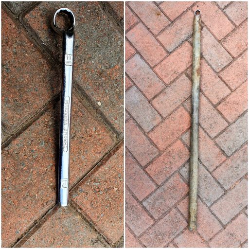
Adapted Spanner
So we adapted a 19mm ring spanner by cutting one end off so we could use it with the pipe for the breaker bar. This worked surprisingly well.
Before we tried to undo the first fixing we dosed each bolt several times with penetrating oil and left it to soak. Do this the day before. Each nut came undone easily. The pain was undoing the nut all the way to get it off with the limited movement we had. It took a long time for each fixing until you could get a socket in there. Start this early.
The front ones have similar fixings but the threads are nowhere near as long so you can use a normal socket. But they were very tight and took a lot of effort to undo completely.
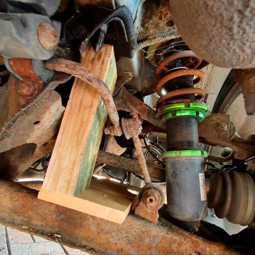
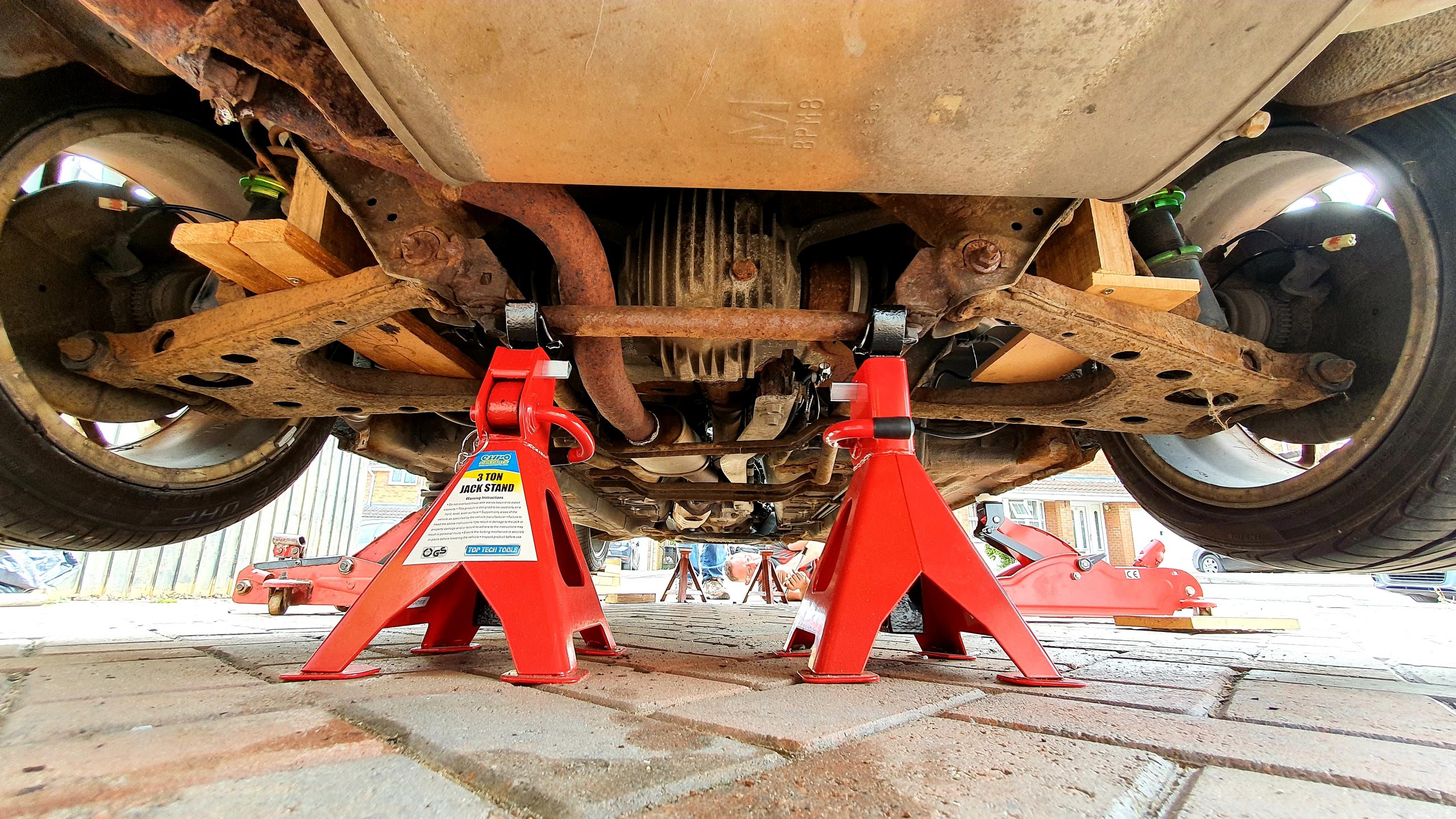
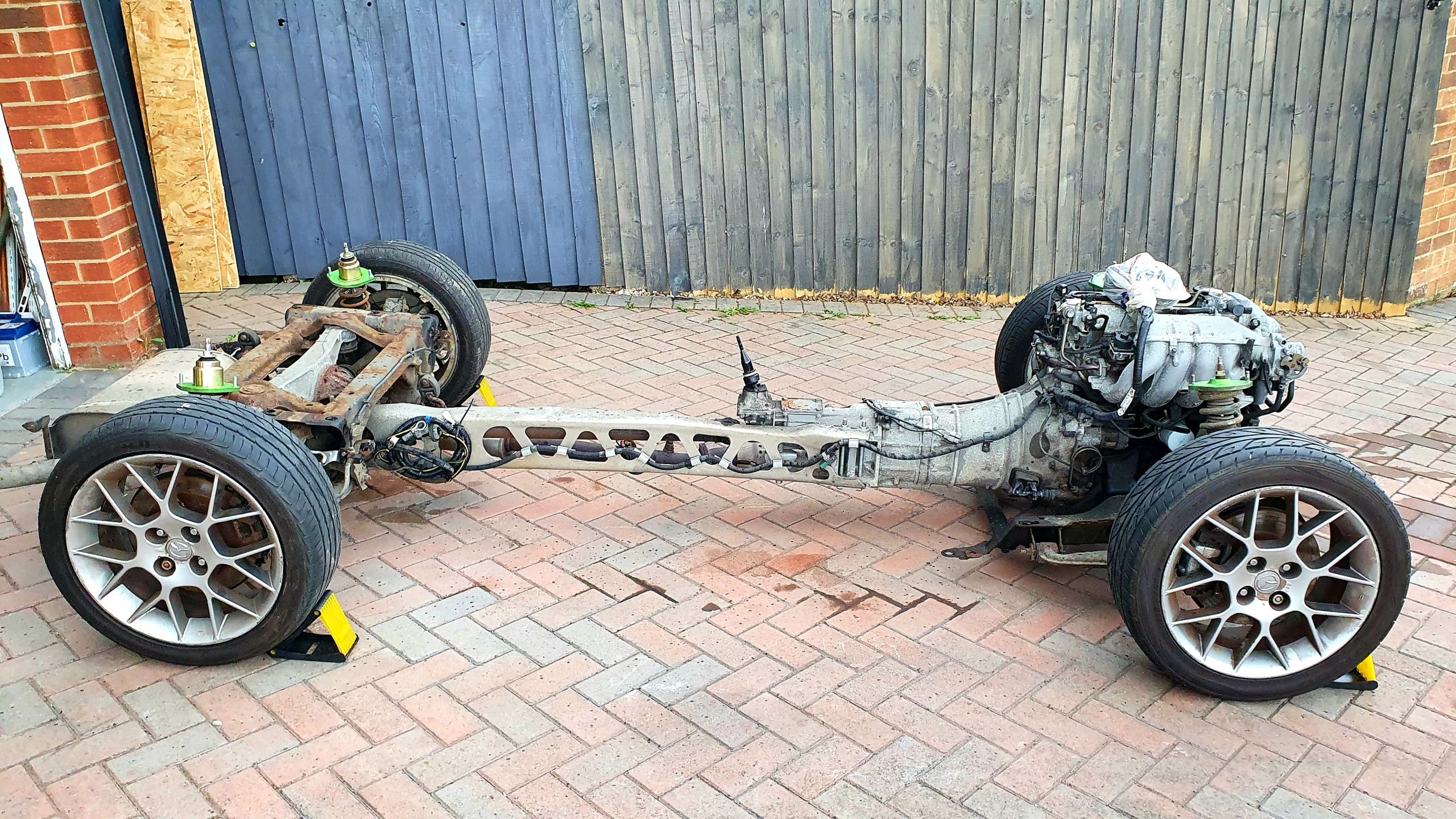
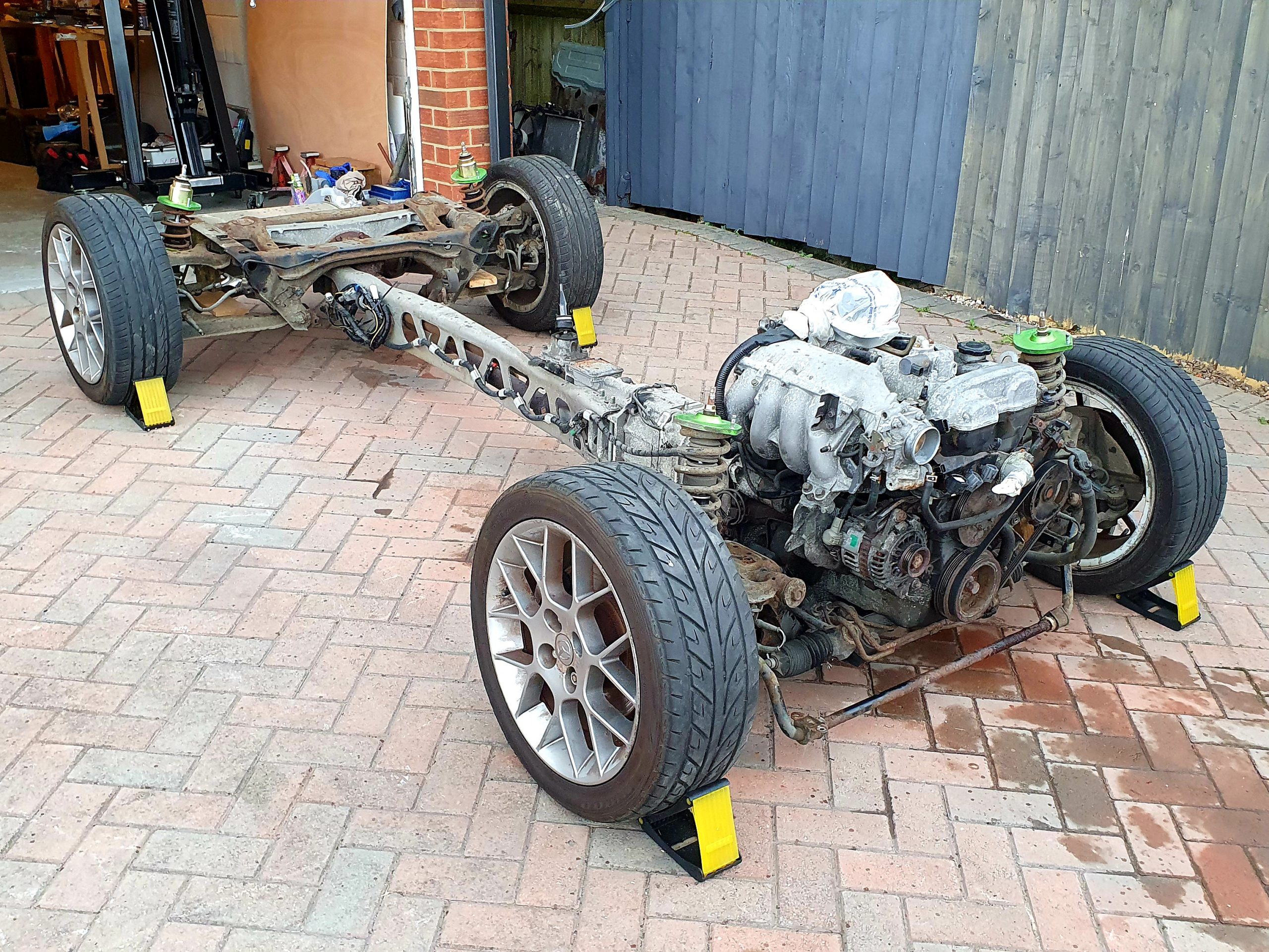
Suspension Support
To support the suspension once the shell is off and to stop it from collapsing my Dad knocked up some suspension supports out of blocks of wood. These basically wedged in between the top and bottom wishbones.
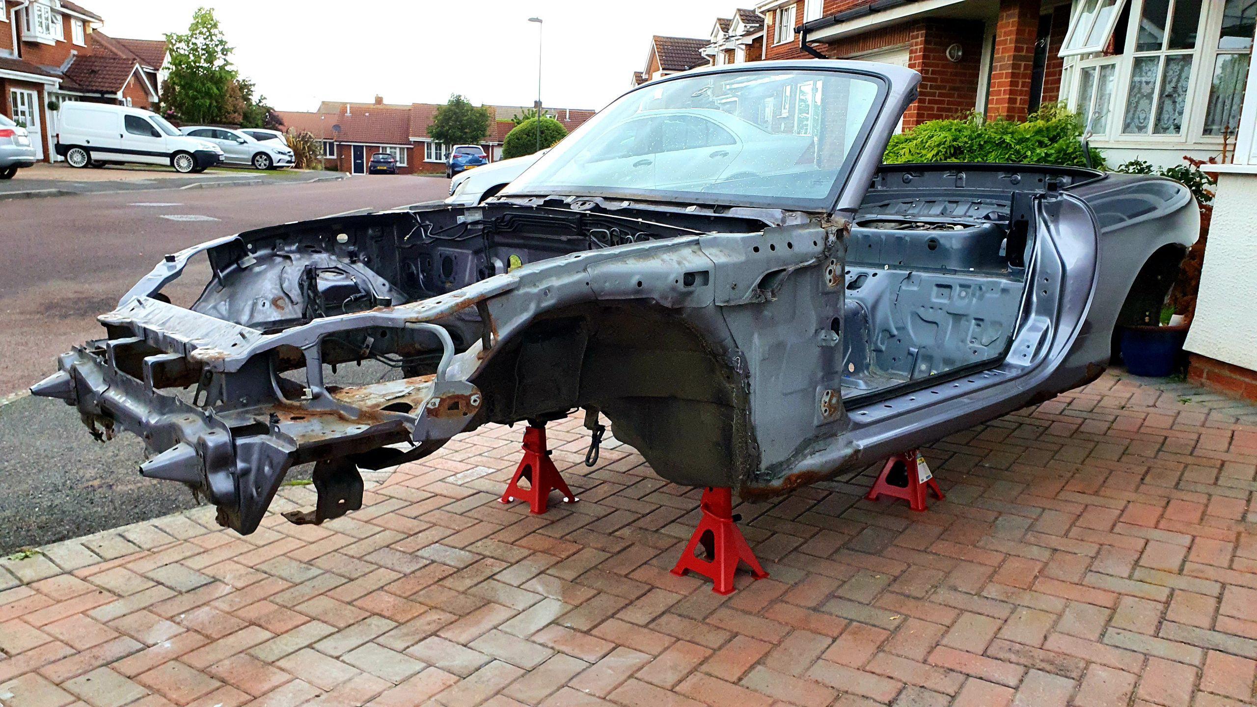
Preparing to Lift
So we now had everything separated ready to lift the shell. The video at the bottom of this post has a good walk-through of the final things we did in preparation for the lift.
We then turned our attention to the lift itself. Now, from my research, the total weight of an MX-5 shell in this state is c. 225kg based on this tread where an Mk2 1999 shell weighed 495lbs. Now assuming that an Mk2.5 is the same as an Mk2. Even if it was slightly heavier it is reasonable to assume it is not heavier than 250kg. Therefore the 1/4T setting on an engine crane can be used.
Looking at the YouTube videos a combination of chains and straps were used to loft the shell, but generally followed the same idea.
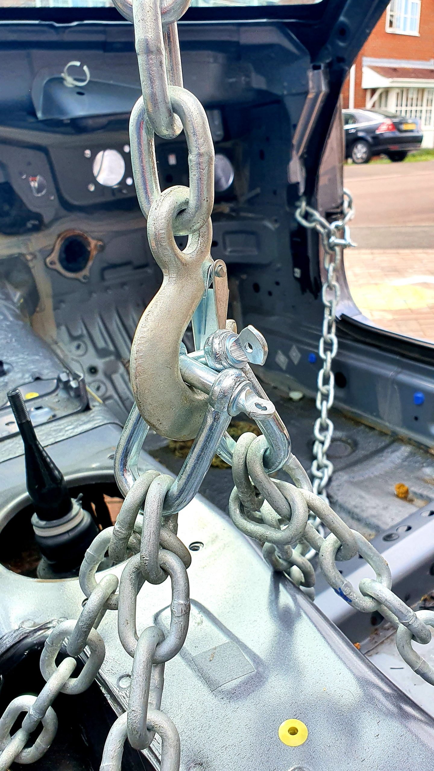
We decided to go with a pure chain approach as it gives strength and ease of connection to the shell. I bought the following items from Screwfix.
- 8mm x 5m Chain rated at 400kg (803HT);
- M10 shackles rated at 500kg (358HT);
- M12 shackles rated at 800kg (858HT).
This was slight overkill for the assumed 225kg weight of the shell. Particularly as the weight will be distributed over 4 points, but that’s the engineer in me!
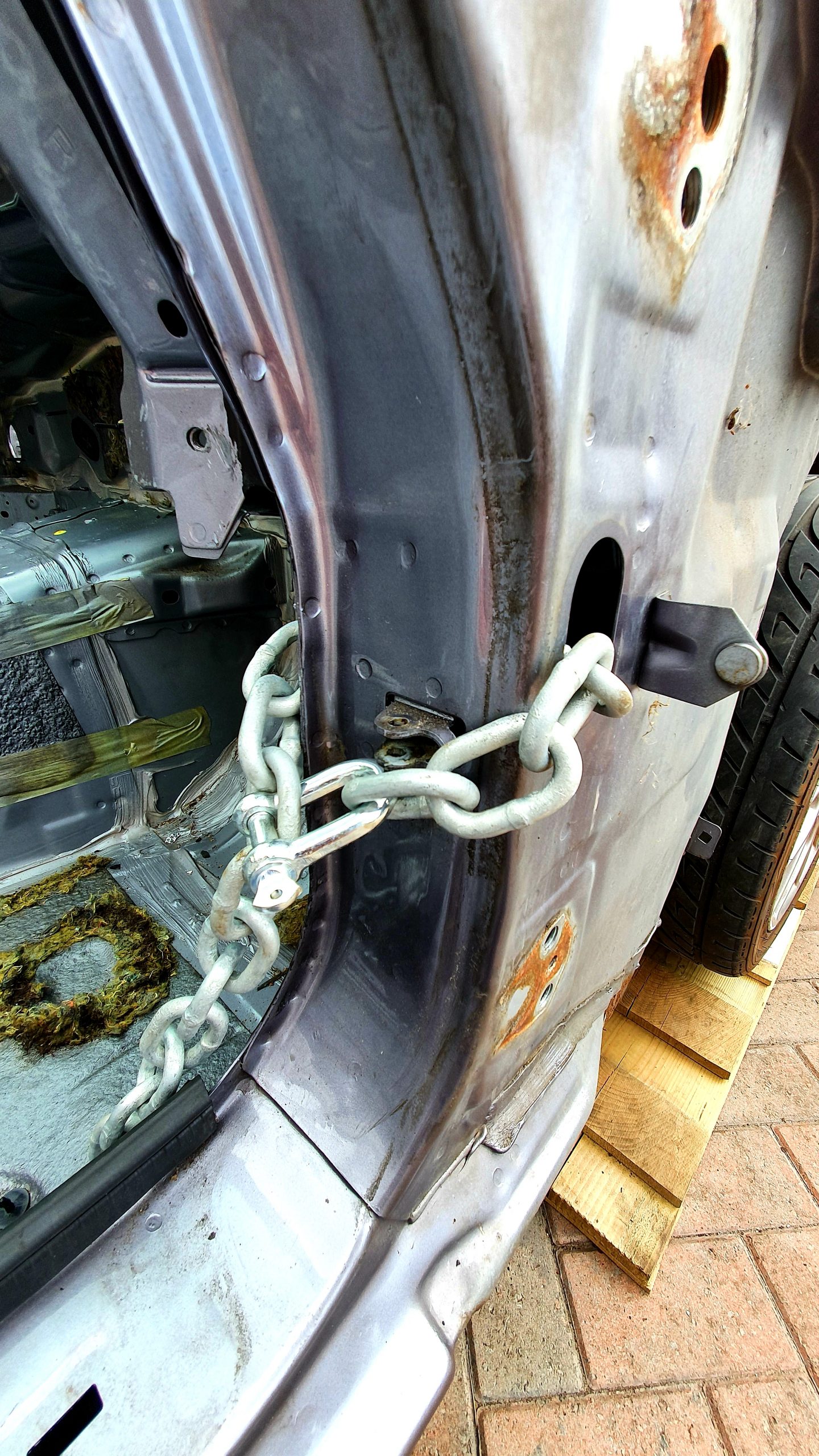
Chain Connections
We came up with a good solution for fixings that were distributed evenly at 4 points. There are holes going through the shell where the door hinge is for the electrical connections. Looping the chain through here was perfect and connect with a shackle.
We then used the seat belt anchor point, where the bottom of the reel connects, not the one on the floor. The M10 shackle fitted through nicely.
Then connected them together with M12 shackles at the top with the 2x M12 shackles going to the hook on the engine crane.
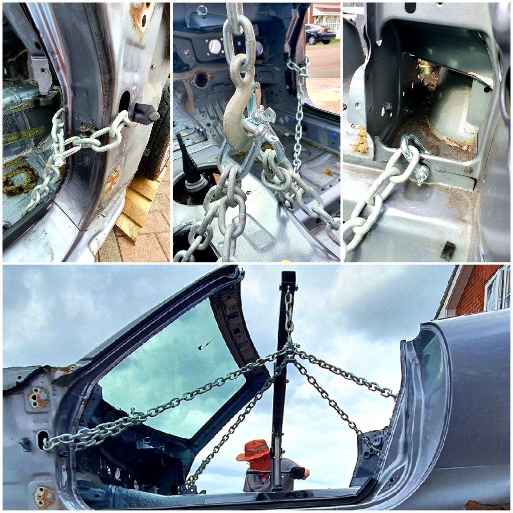
Engine Crane
A friend kindly gave me his 2T Engine crane to use which was perfect as it had a great 1/4T reach. This might be more of a struggle with a 1T crane.
We decided to do the lift with the car on the floor on its wheels. We felt this was the safest way given the slightly sloping drive. The YouTube videos we watched raised the car on jacks then gradually lowered the sub-frames with the crane in position. We weren’t convinced by this approach.
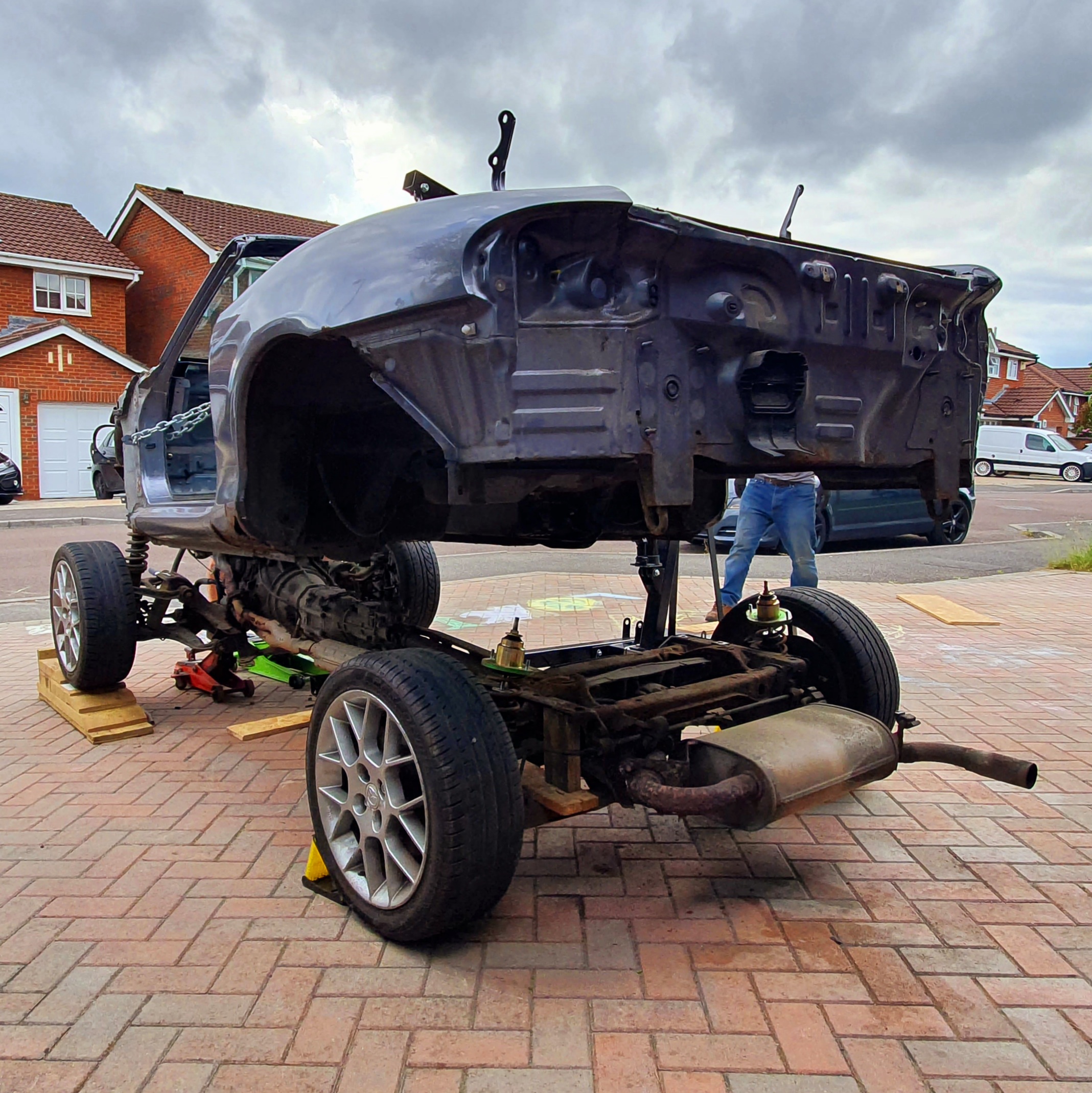
The one issue we had was the car was too low for the crane legs to fit underneath. The problem with aftermarket adjustable coilovers… So we resorted to putting the front wheels up on ramps and the rear wheels on the ground. This gave us the clearance we needed.
With the crane in position, we attached the chains to the hook. We then adjusted the number of links on the chains until the length was even and the hook central to the vehicle.
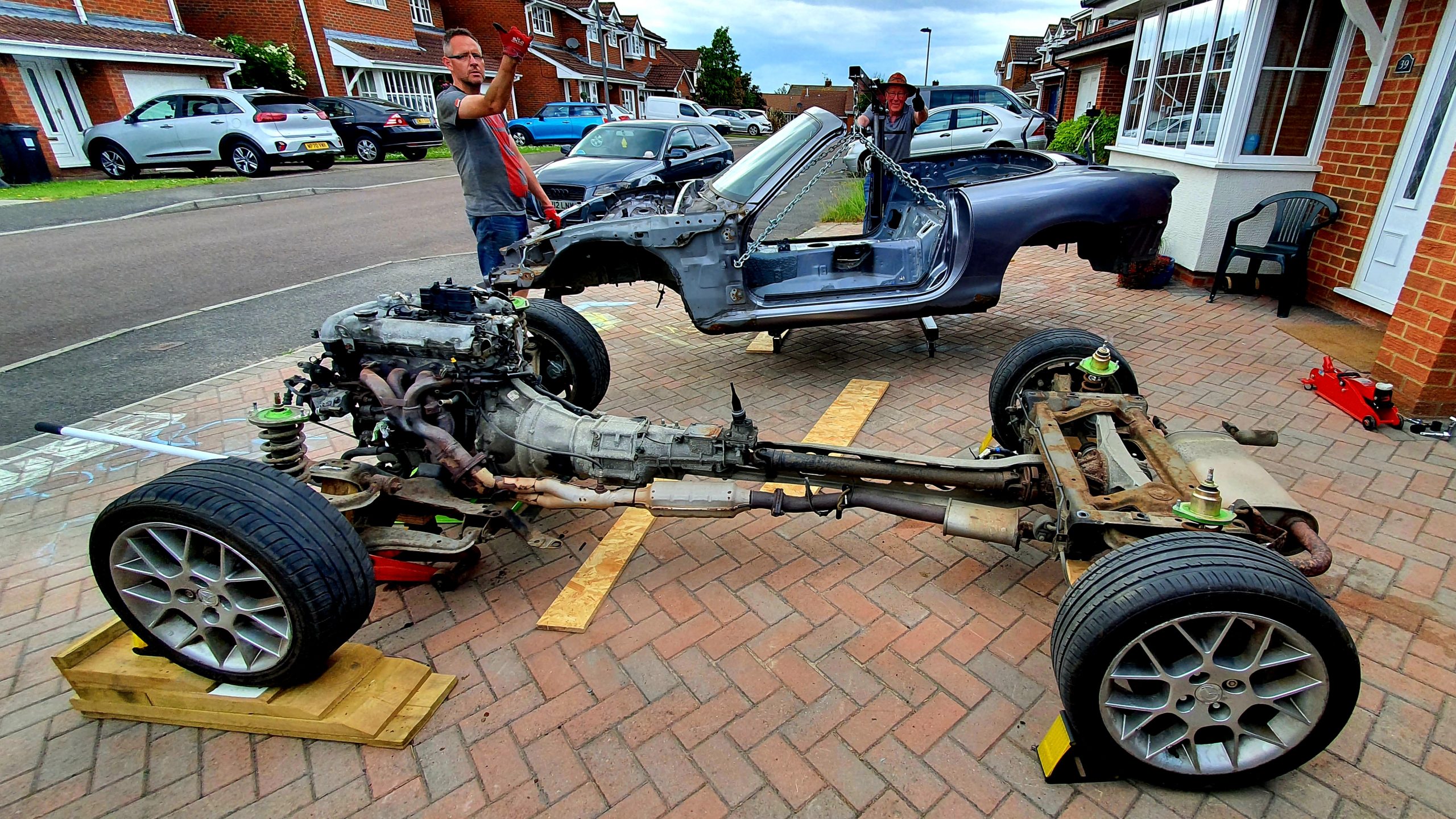
The Lift
My Dad started lifting the crane and took the strain on the chains. The shell started the raise… We then found an encouraging lift on the front corner helped the shell separate from sub-frames with a convincing clonk!
We did a quick check before raising it further to make sure nothing was caught or still connected and it all looked good! It was actually working surprisingly well. The chains were perfectly balanced with the first attempt!
We kept raising the shell until we had a significant gap and were almost clear of the engine at the front. At this point, the shell wanted to swing forward due to the sloping drive. Dave did an admirable job of holding it while I took a few snaps!
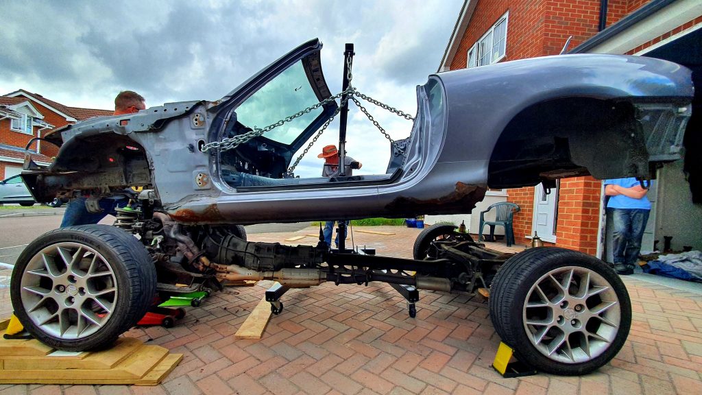
We then lifted the shell clear of the engine and between us moved the crane backward away from the roller skate. Job complete first time with no issues!

End of Day 3 Summary
So that is it for Day 3 of stripping my Mazda MX-5. We managed to get the shell of the vehicle in 3 days, which was our optimistic target. So we were very pleased!
Videos
Here is a walk-through video showing all of the final things we did in preparation to separate the shell from the sub-frames/ roller skate.
Here is a time-lapse video of us stripping my Mazda MX-5 donor vehicle and finally separating the shell from the roller skate.
Gallery from Day 3


Summary of Build Costs and Hours
Here is a summary of the costs and person hours (total number of hours for every person that has helped) for the build so far. This should hopefully help others with the planning of their builds, by providing cost and time actually incurred for this build. A more detailed breakdown of all the costs and hours worked on the build to date can be viewed here.
| Person Hours Worked This Post | |
|---|---|
| Donor Strip Day 3 (3 people) - Preparation and Separation of Shell from Roller Skate | 31 hrs |
| Tool Costs This Post | |
|---|---|
| 8mm x 5m Welded Chain, M10 and M12 Shackles for Shell/ Engine Lift | £47 |
| Totals | This Post | To Date | All Posts |
|---|---|---|---|
| Person Hours Worked | 31 hrs | 94 hrs | 500 hrs |
| Car Build | £0 | £765 | £13,956 |
| Tools / Consumables | £47 | £215 | £470 |
| Total Cost | £47 | £980 | £14,426 |
