
So, after we had fitted the seats we moved onto installing the MK Indy differential. Now this is pretty clearly documented in the manual so it really was just a follow the instructions.
One thing I did a while back was refurbish the MK Indy differential and other parts from the MX-5 donor vehicle that would be needed for this stage of the build. Here is a quick overview of what I refurbished and how the install of the MK Indy differential went.
Donor Parts Refurbished
- Differential
- Drive shafts
- Rear uprights
- Front uprights
Differential
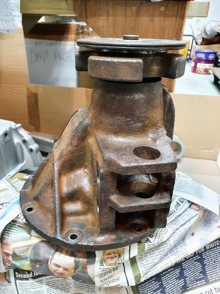
Painting the Differential
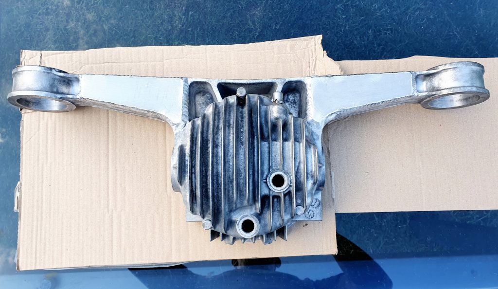
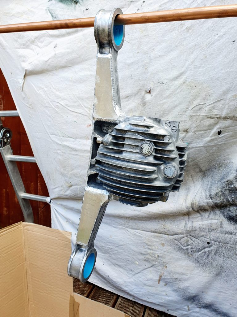
So my donor car was a 2004 Euphonic Mk2.5 so it came with a Limited Slip Differential, a nice little bonus. I had already sent it away to MK to be modified and strengthened to futureproof it. So it now needed a coat of paint, fresh seals and rebuilding.
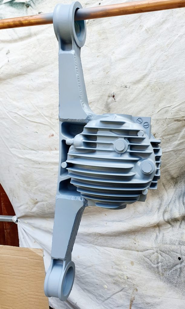
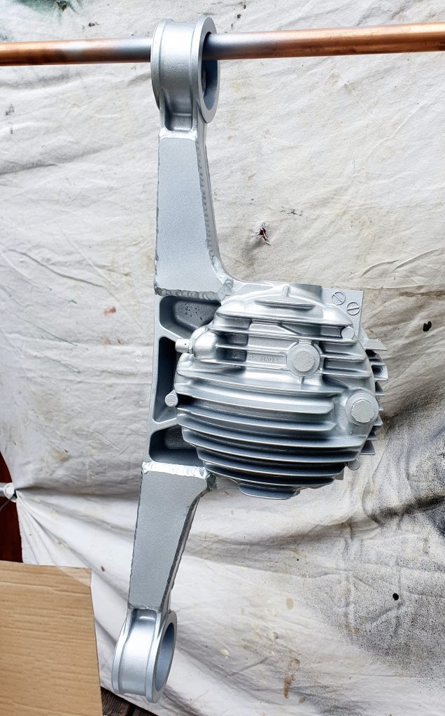
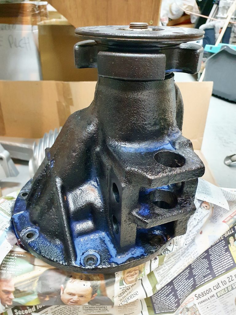
Luckily the weather was a lot warmer outside when I did this so I setup a paint Booth in the garden and spray painted the differential along with the sump which had also been modified by MK to be the shortened sump for more clearance.
For the aluminium casting I used the same spray paint as I did for the engine which was a 3x part VHT paint system with primer, silver colour coat and clear laqeur. I then used a hammerite smooth black direct to metal paint for the steel casting. My Dad had very kindly already done a cracking job of cleaning it up for me. Before applying the black hammerite I used the Hammerite Kurust on the steel casting to give the paint a good finish to go on.
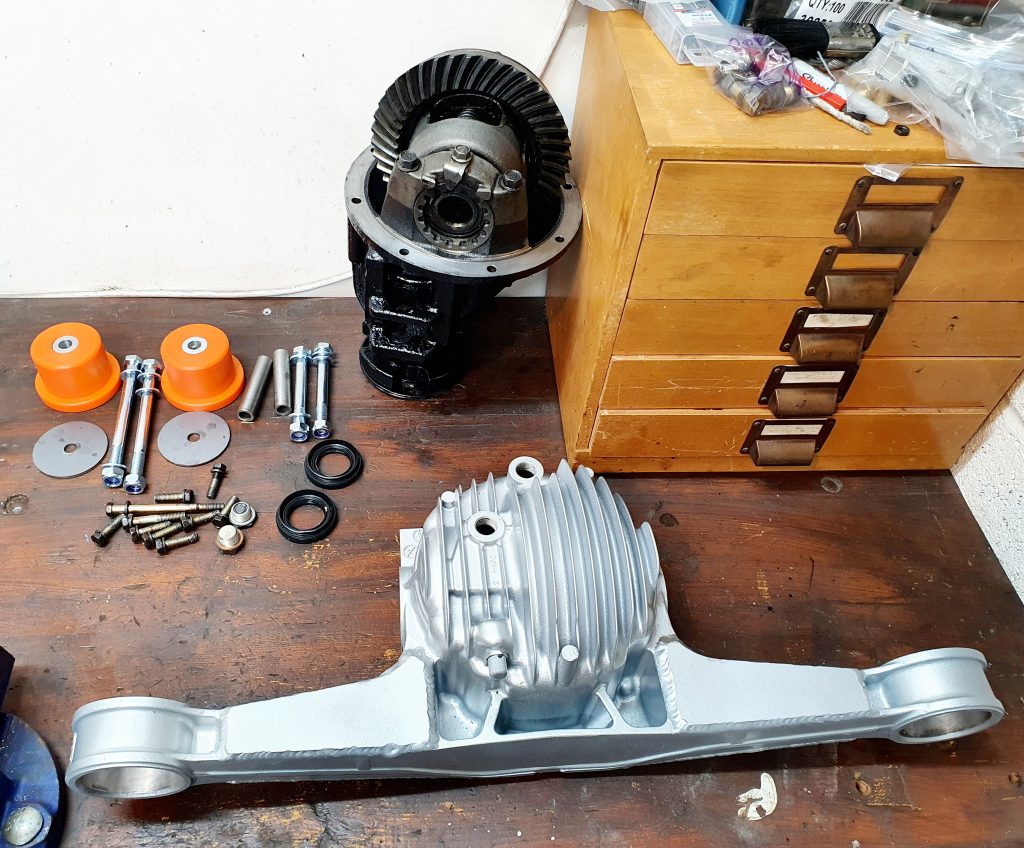
Re-building the MK Indy Differential
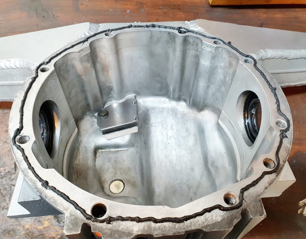
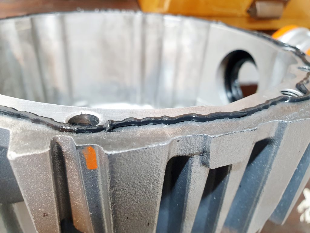
Once I had painted the casings I set about re-building the diff. This was pretty straight forward by pressing in the new seals with a block of wood and a rubber mallet. Then installing the main differential mechanism into the steel casing. Next I applied a thin bead of RTV liquid gasket which was actually Mercedes RTV left over from a job on my merc not that long ago. I then carefully mated the 2 parts together and added all the screws finger tight initially. Then went round with a torque wrench and tightened them all in a star pattern to 25Nm (as specified here).
The final piece was to insert the new silicon bushes into the MK Indy differential. This is a case of following the manual but the measurement for the crush tube was wrong and should be 57mm instead of 45mm.
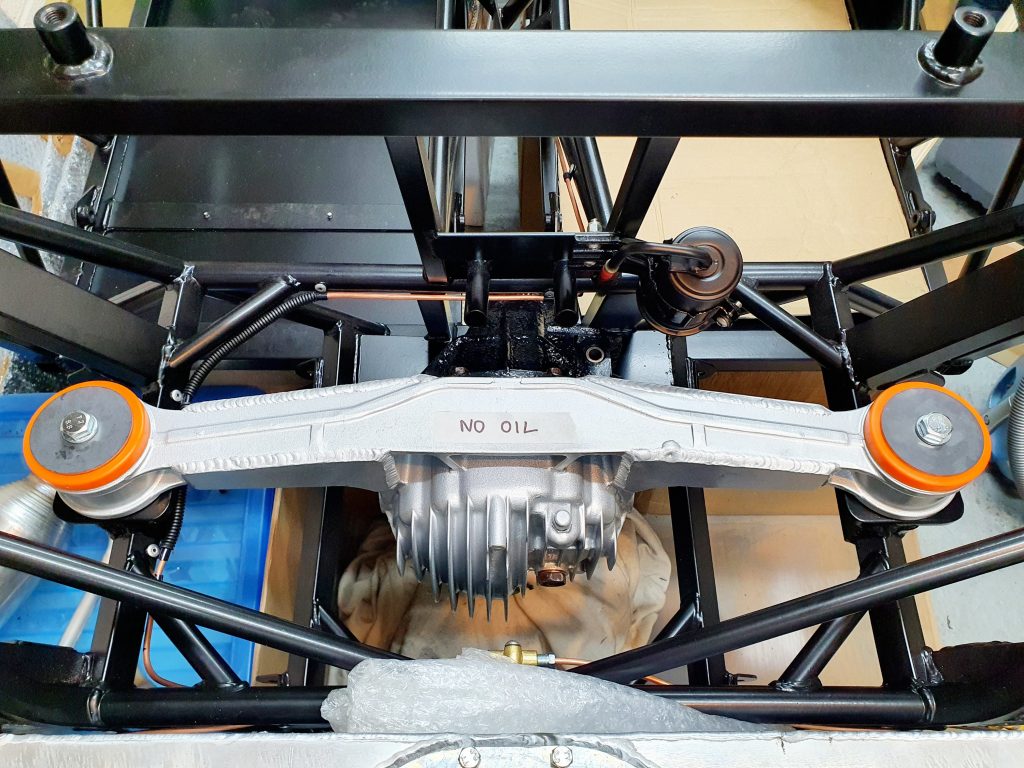
Installing the MK Indy Differential
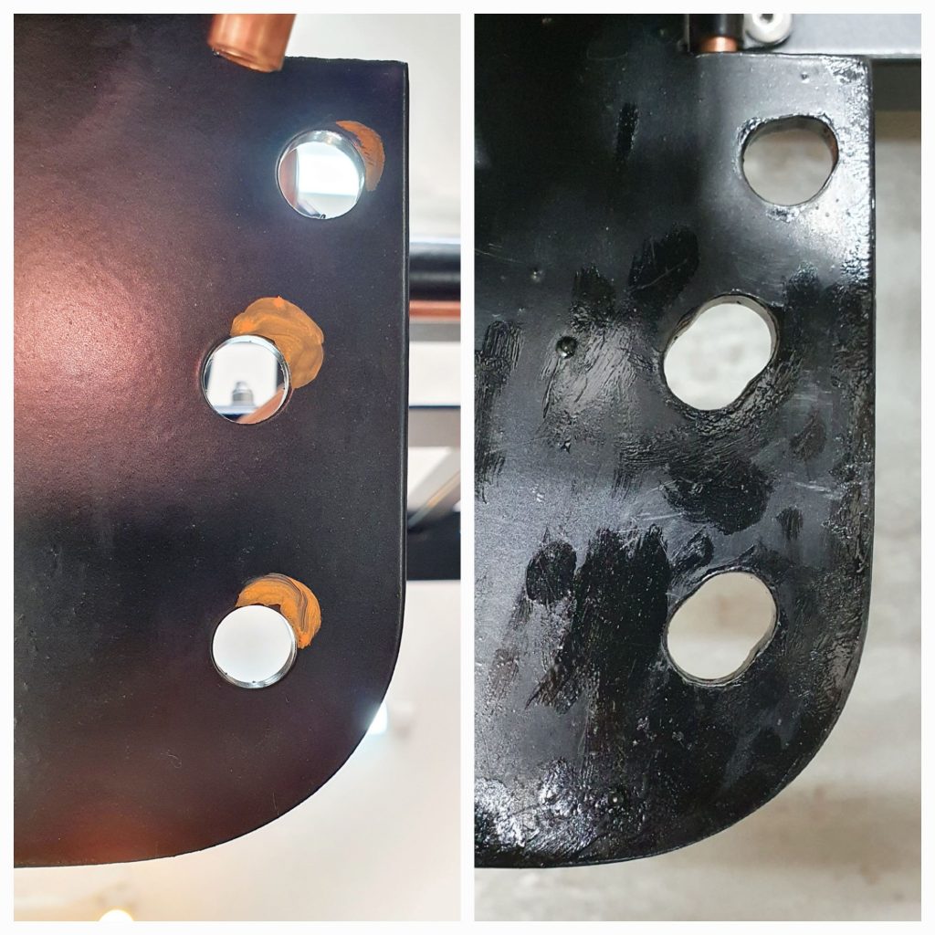
We then did a test install of the differential in the car to check for alignment as I know some of the other builders had issues with the mounting holes not quite lining up with the chassis. Sure enough when the MK Indy differential was in and the 2x main bolt through the ears were through the chassis the holes through the bottom base plate didn’t quite align.
This is not a big issue and just needed the holes in the base plate elongating to accommodate.
I marked out the location for the elongation from underneath then used a round file to open up the holes the correct amount. I then added some hammerite direct to metal paint on the elongated holes to protect the bare metal.
Shim Required
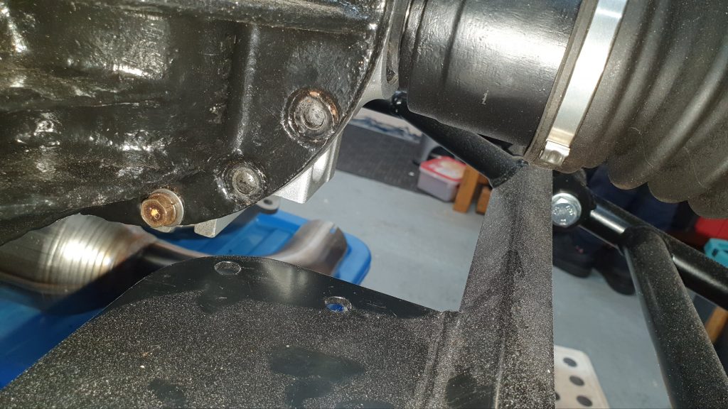
We then test fitted the differential again and this time the holes lined up. The next problem was with the ears of the differential flat on the top mounts, there was a small 1mm gap between the bottom of the diff and the chassis. If I made the bottom of the diff flush with the chassis the ears did not sit flat on the top mounts.
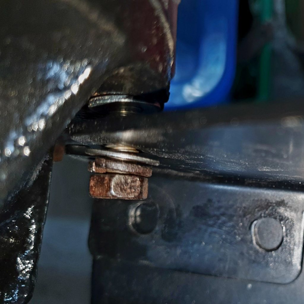
Now, I know from the builders groups that you need to make sure that you get the ears completely flat on the top mounts otherwise it can lead to excess strain on the casing and can crack the diff. So I made sure that the ears were flat in the top mounts and then created an aluminium shim to go under the differential between the chassis to allow both top and bottom mounts to be flush with the chassis.
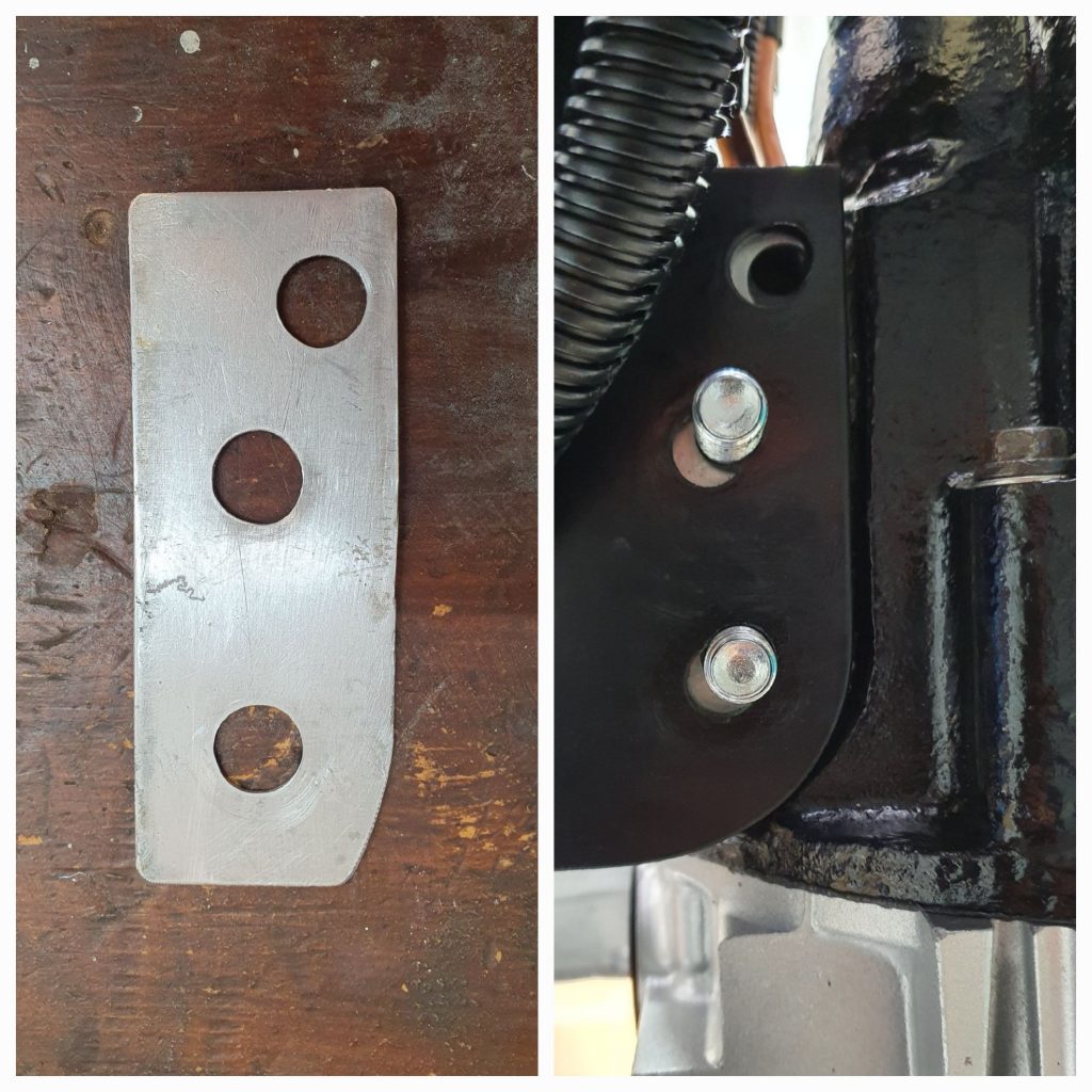
This worked well and allowed the diff mounting bolts to be torqued up to the correct specs. I then added plastic nut covers to all the diff to chassis bolts from underneath to add some additional protection.
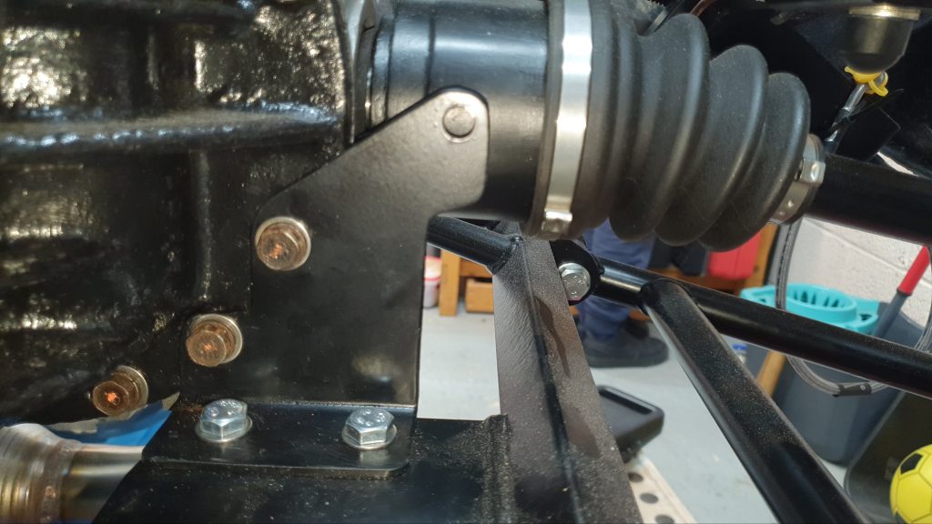
Differential Additional Bracket
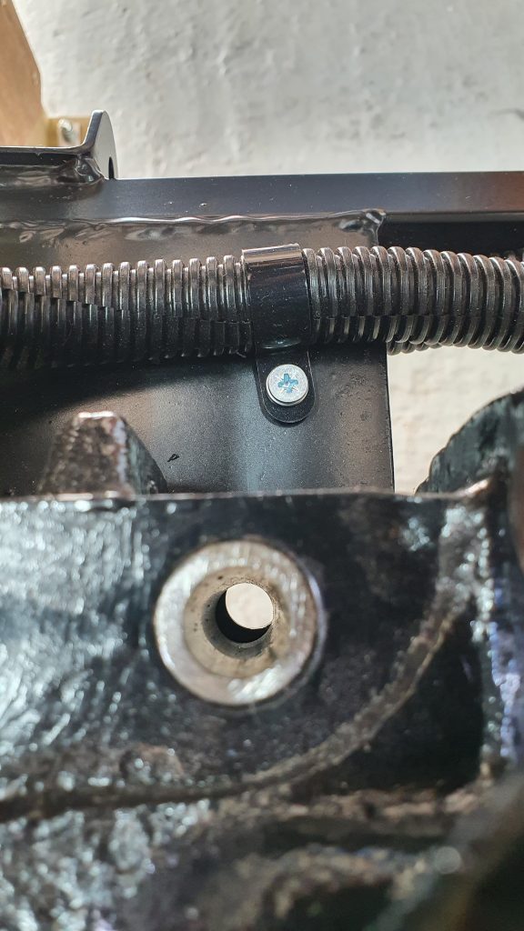
There is also an additional bracket in the kit which also provides a bit of additional strength plus a mounting point for a 3rd party speed sensor. Now I don’t need the speed sensor right now as I will be using the std MX-5 one but at least this adds greater strength and future proofs for a sensor later if needed.
You can see in the photo above the mounting location for the bracket which mounts to the chassis at the bottom and to 2x of the diff casing bolts – which are removed in the photo. I had to elongate the bottom holes of the bracket to line up with the holes in the chassis as they were off by about 3mm. I painted the bare metal of the elongated holes for protection then once dry fitted the bracket in place. Due to the slight recess in the diff casing where the bolts go I added a washer between the diff casing and the bracket like below.
I then torqued up the diff casing to 25Nm (as specified here) and the M8 zinc plated bolts with nylocs to 20Nm (as specified here).
Driveshafts
So the driveshafts from the MX-5 also needed a bit of a refurbish. The only problem I had was one of the drive shafts just wouldn’t seperate from the rear upright. After a bit of research it appears this is a common problem with MX-5s.
Removing Driveshafts From Uprights
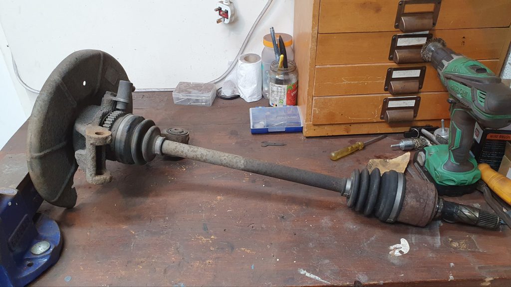
One of the driveshafts came out reasonably easily with a bit of gentle persuasion with my hub puller. The other drive shaft broke my hub puller by snapping a linkage trying to get it out. So the only way I manged to get it out in the end was with a lot of penetrating oil and a lot of brute force.
I mounted the wider end in my vice and supported the other end with a block of wood clamped to the bench. So, the drive shaft was hanging down. I then placed a metal block on the end to provide a bit of protection to the driveshaft end and started hitting it reasonably hard with a club hammer. In the end this ended up being a sledge hammer going full tilt which eventually broke the seal and it gradually came out. It was a massive relief.
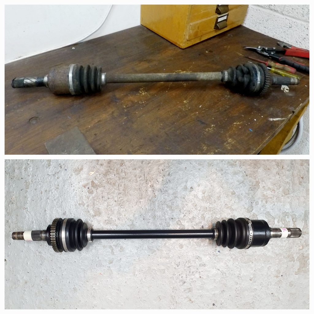
Refurbishing Driveshafts
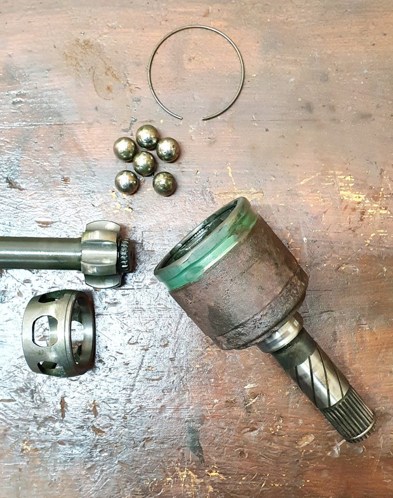
So, now I had the driveshafts seperate it was then a case of striping them down and cleaning them up. I found a great YouTube video which explains how to do this for the Mk2 driveshafts which is close enough. There are 2x different ends to the driveshaft. One that is fixed the other which is variable to allow for movements in the wheel end with the suspension. There are a couple of subtleties which are different in the Mk2.5 driveshaft to the Mk2 (from the video. These are mainly with the circlips and securing mechanism.
Once stripped apart I cleaned up the shafts and the housing ready for paint. This was just a case of using course sandpaper and a wire brush. I then used more of the Hammerite Kurust to give a good paintable surface and masked them up for paint. I used some Simoniz satin black spray paint this time to give a good ‘like new’ finish.
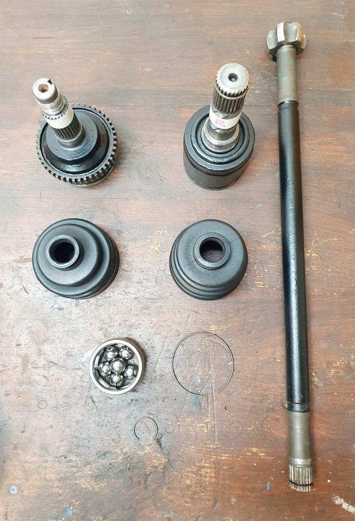
I was really pleased with how the driveshafts came up, the finish of the satin paint was like new. I was fortunate to have good condition boots with no cracks so I cleaned them up well. Then I used some back to black rubber condioner from my car cleaning kit and it brought them up really well. Next was reassembly.
Reassembly of Driveshafts
The first thing to do is to make sure the rubber CV boots are on the shaft before you start assembling the bearings. Make sure you have got them the right way round for the right end. I then assembled the bearing in the reverse of the way they came out, making sure the circlips are firmly in place.
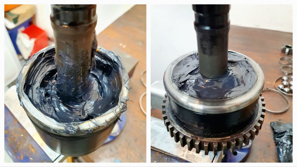
Next I added approx 80g of Comma CV Grease to each end. I did this by squirting grease into a sandwich bag and cutting a small bit off the corner then squeezed out the grease like a icing piping bag. This allowed the grease to easily get between all of the ball bearings until it oozed out the top.
Next I slide the CV boots over the joint and made sure they sat well into the grooves in the metal. I then got some new CV boot clamps to install and crimped them up tight around the metal groove.
That was it, completely transformed and restored drive shafts which lool like new. I was really pleased with the way they came out.
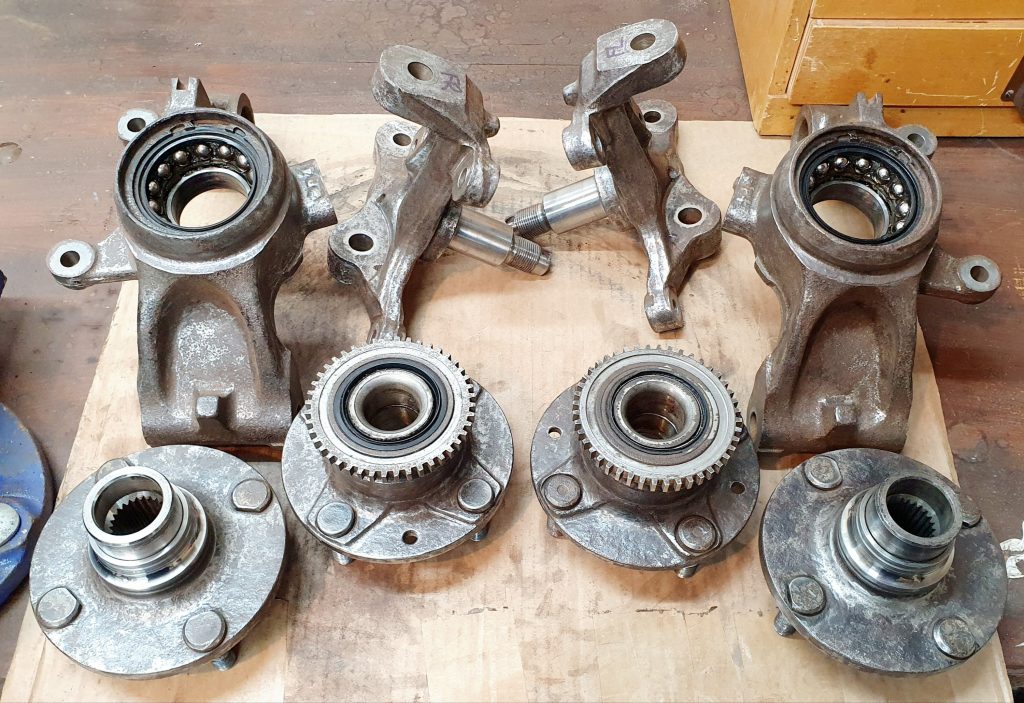
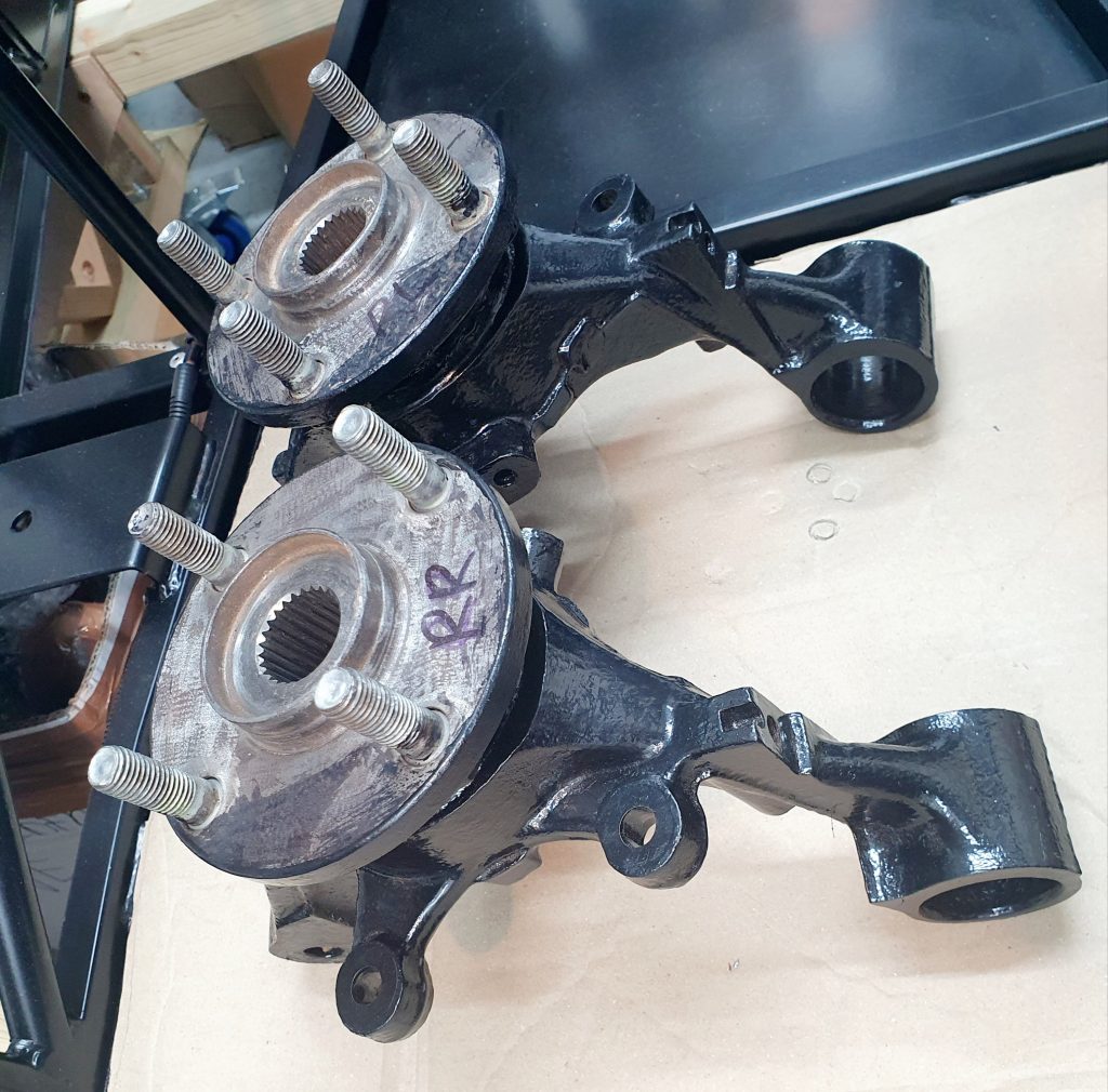
Front and Rear Uprights
So the final thing I refurbished was the front and rear uprights which include the hub bearings. The first thing was to clean up the uprights. I used a wire brush drill attachment, a dremel with wire brush attachment, various wire brushes, Gunk degreaser and a lot of elbow grease. Eventually I made them look like this.
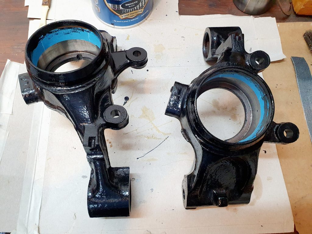
I then removed the rear bearings with a bearing press as these would be replaced and set about painting them. I used the same Hammerite Kurust to take any rust back to a good metal surface ready for paint. Then I used a hammerite straight to metal smooth black paint to cover the uprights. I painted the rear ones whilst my Dad very kindly offered to paint the front ones – thanks Dad! This paint is great as it doesn’t need and primer. It goes on really well and gives a nice finish and doesn’t really smell that much. Plus it drys quite quickly.
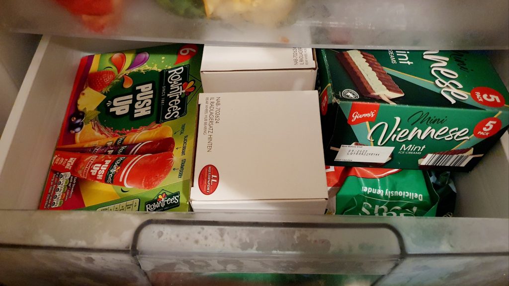
Installing Rear Hub Bearings
Next I set about fitting the new LL Motorsport bearings. I read that putting the new bearings in the freezer for a few hours before hand can help with fitting them into the upright, so I gave this a go.
I then used the bearing press my friend Robert kindly lent me (thank Robert) to press them in after applying a thin coat of bearing grease to the inner face of the upright.
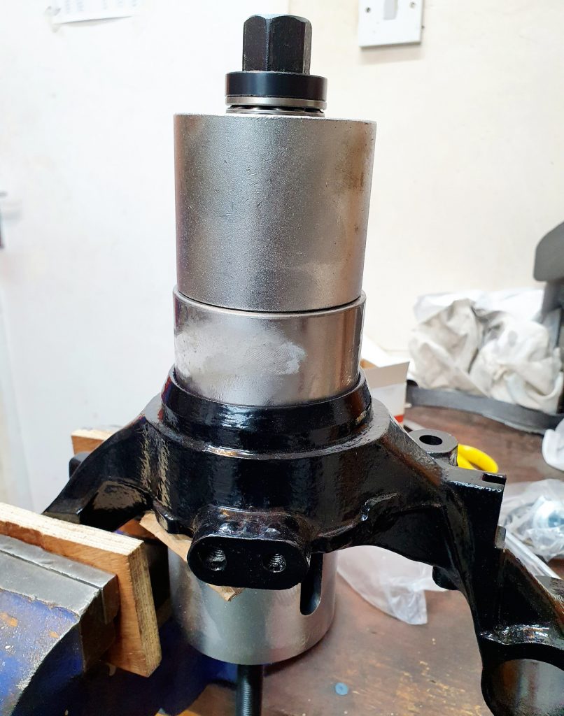
This actually worked really well but I’m not sure the freezer really helped that much as it was so cold there was frost on it and this made the bearing grip the sides probably too much. Maybe I left them in the freezer for too long! Anyway the bearings went in OK in the end.
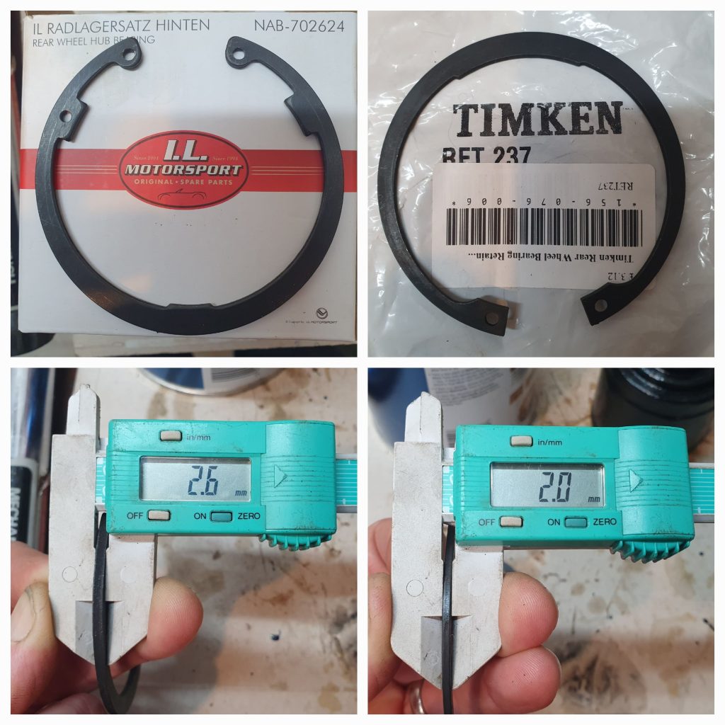
Bearing Retaining Circlips
The only issue was that even with the bearing seated all the way to the bottom the supplied circlip would not fit in. It seemed too thick. The original circlip fitted in fine as they were 0.5mm thinner. But they were pretty rusty so I didn’t want to reuse them. I eventually found some other circlips by Timken online which seemed thinner on the spec. So, I took a punt and ordered them. They turned out to be perfect and fitted well being only 2mm thick instead of 2.6mm. It made all the difference and were almost identical to the ones I took out.
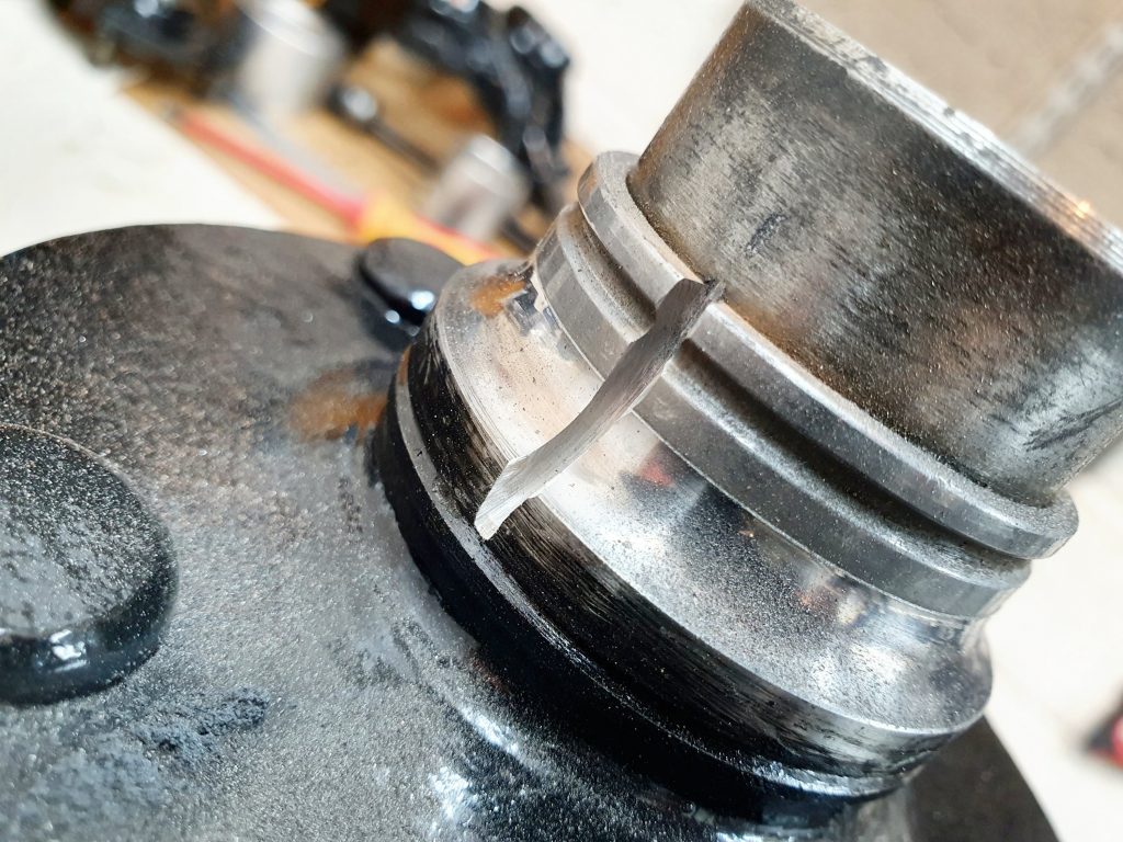
I then had to remove the bearing race from the wheel end. Reading up online about this the easiest way is to cut if off with a dremel and small cutting disk. This actually worked well and once it was nearly through you just tap it with a small chisel and it pops apart. This allows you then to just use a flat balde screwdriver to take of the race.
The final thing was to press the wheel ends into the upright and new bearings. This was quite easy with the bearing press again.
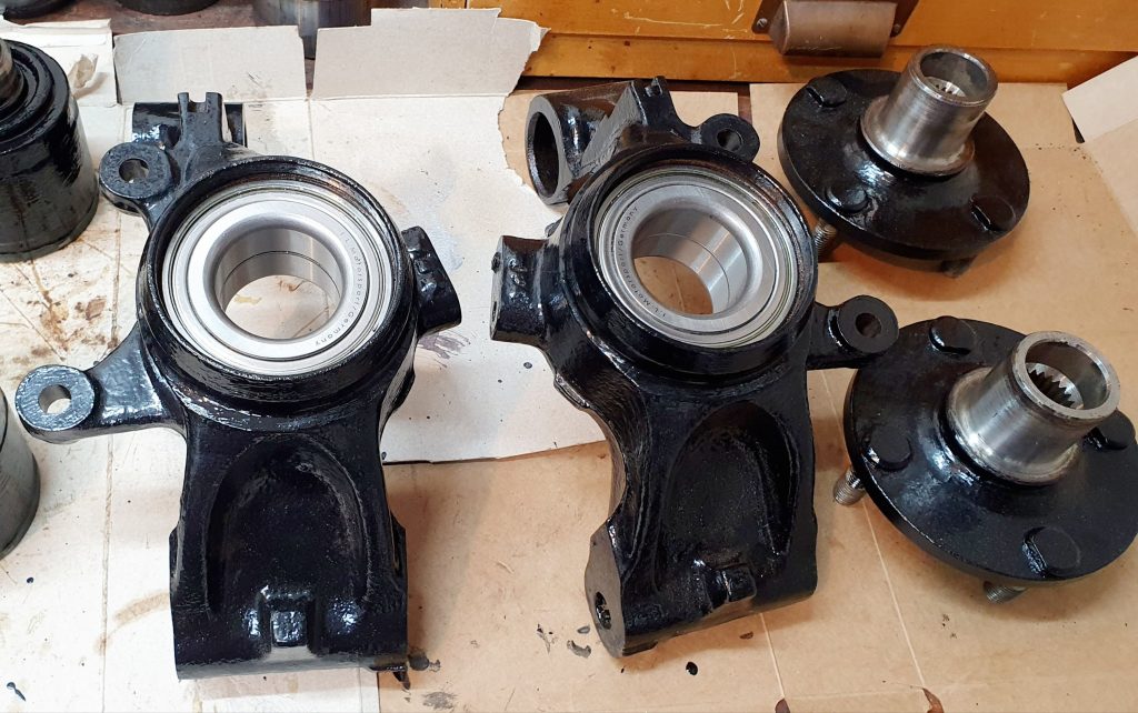
The rear uprights were complete. The process for the front uprights was similar but the bearing does not need to be replaced. It is not a sealed unit like the rear, instead I simply stripped them down and replaced the grease and rebuilt them.
All these parts are now ready for the next stage which is the build up of the rear suspension.
Summary of Build Costs and Hours
Here is a summary of the costs and person hours (total number of hours for every person that has helped) for the build so far. This should hopefully help others with the planning of their builds, by providing cost and time actually incurred for this build. A more detailed breakdown of all the costs and hours worked on the build to date can be viewed here.
| Person Hours Worked This Post | |
|---|---|
| Clean, Paint and Rebuild Driveshafts | 6 hrs |
| Clean, Paint and Assemble Differential | 7 hrs |
| Clean, Paint and Assembly Front and Rear Uprights | 15 hrs |
| Car Build Costs This Post | |
|---|---|
| CV Boot Clamps | £13 |
| Hammerite Black Smooth Paint | £18 |
| Diff Drain and Fill Plug Washers | £4 |
| Tool Costs This Post | |
|---|---|
| Comma Bearing Grease | £8 |
| Comma CV Joint Grease | £10 |
| Clic Hose Clamp Pliers | £17 |
| Torque Wrench 3/8 10-60Nm | £35 |
| Totals | This Post | To Date | All Posts |
|---|---|---|---|
| Person Hours Worked | 28 hrs | 302 hrs | 500 hrs |
| Car Build | £35 | £12,536 | £13,956 |
| Tools / Consumables | £70 | £459 | £470 |
| Total Cost | £105 | £12,995 | £14,426 |

Hi, following your blog with great interest! I’ve just started an RX5 build – mk 2 engine, NA initially, but building it ‘turbo ready’.
Just trying to finish engine paint and rebuild before making too much progress on the build, but ready to raptor paint the chassis underside as you did.
I’ve refurbed the diff – does it sit metal against metal on the main mounts? I assume so as the orange bushes are top hat not cotton reel shaped? Thanks. Adam.
Hi Adam, sorry for the delay in responding. It’s great to hear you are making good progress. Yes the main mounts, where the orange bushes are, sit flat metal on metal and the orange bushes are top hat only. Just make sure they are completely flat and bolted down first. Then look to see if the bottom mount is flush on the chassis. If not then shim it out at the bottom as you can see in my photos. If the top mounts are not flat you will crack the ‘ears’ of your diff. Good luck!