
After achieving a successful first start of the car, it was time to sort out the MK Indy wiring harness and strip out all the bits I didn’t need in the standard MX-5 harness. This was a slow burn, little and often, part of the build over the autumn and winter period.
There is an option to buy a custom MK Indy harness from MK Sportcars, but at £600 and with me being an electronic engineer, I felt drawn to saving the money and stripping out the standard MX-5 harness. I knew deep down I would probably end up enjoying doing it once I got started!
Now, I have the Mk2.5 loom which is very similar to the Mk2 loom, but there are some differences. The MK manual Part 3 is currently based on the Mk2 loom only but does have a lot of good detail in it and what to remove from where.
As I completed the strip down of my loom I captured the differences for the Mk2.5 loom and will try to summarise the main differences in this blog at a high level. I am also supporting MK in updating the Part 3 manual to include the Mk2.5 differences so other builders can benefit. Watch this space…
The following guidance and differences are based on the current MK Indy Manual Part 3 version 2022-01 dated May 2022.
Working Area
I’m not blessed with a massive double garage, and I knew I wouldn’t get away with leaving the harness out in the house somewhere, so I had to think creatively to make space to work on the harness.
Others on the forums had suggested building a table over the car to work on. This sounded like an ideal solution for me, and I had some spare plywood and stud work to use. I set about making a table that would fit on the car and came up with the following solution.


This provided an area approx 1.5m x 1.5m to work on, which was an ideal size to lay the harnesses out and at a good working height.
Separating the Harness
I first split the harness into its constituent parts. There are 5x sections to the harness:
- Engine Loom – This is the main engine loom, connecting all the sensors for the engine. Only minor modifications are needed to this loom to remove the Power Steering Pump connector and the AC Condenser Fan connector.
- Power Loom – This has the main fuse box and connections to the battery and starter motor. Only minor modifications needed to this loom to remove ABS connectors and additional rear loom power connector.
- Rear Loom – The loom for the rear of the car, which includes rear lights and fuel pump connectors. Quite a log gets stripped out of this loom, including the rear heated window, radio Antenna, seat controls and sensors.
- Dashboard Loom – This has the hazards and fog light switches and other connections. Relatively minor changes to this loom.
- Main Loom – This is the main Loom that was inside the car for everything else. It has the passenger fuse box and most of the connectors for all the equipment inside the car. This loom has significant modifications, and it is the loom you will spend the most amount of time on. You will know every intricate part of this loom and what it does by the time you have finished!
Overall Aim
I thought it was worth starting with the overall aim of what you are trying to achieve with the MK Indy wiring harness adaption. It can be quite overwhelming at the start when you see the sheer size of the harness laid out in front of you.

At the simplest level, you are removing all of the electrical cabling and connectors from systems that you won’t need for the MK Indy configuration. The main things you are removing are:
- Door, boot and bonnet switches/ connections and interior lighting.
- Heated rear window, heated seats, and seat sensors.
- Radio equipment, speakers, antenna.
- Heater Blower system.
- Powered steering
- Headlight beam adjuster
- Door locking systems
- Window and mirror controls.
- ABS System
- Airbags
- Alarm and Keyless Unit (Mk2.5 Additonal)
- Optional: Windscreen wipers and wash – if you don’t plan to have a windscreen.
Before and After
In general, you are trying to get the main Loom from this:
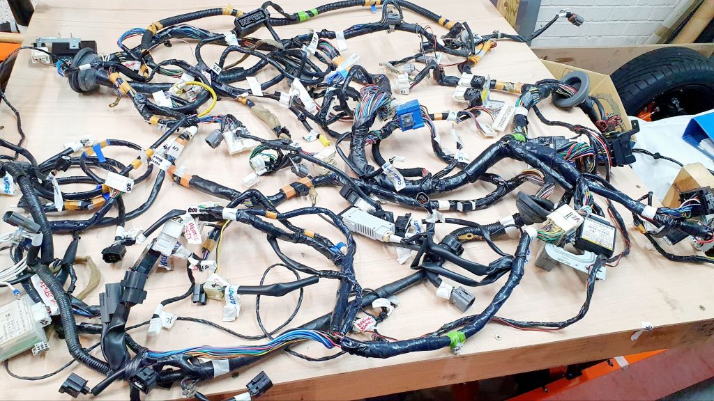
To something like this:

As an estimate, it took me circa 26 hours of labour effort between these 2 photos to strip back all the looms.
General Approach and Tools
The approach taken in the manual is to remove all unnecessary cables and connectors from the loom. This is done by 2 main methods:
Method 1: Unpick from Connector
This is removing the cable end connector pins directly from the plug to remove the individual cables directly from the loom. This is a very neat solution and very easy and quick to do once you get the hang of how to do it. Nearly all the connectors have the same approach to securing the individual pins into the connector housing.
Now, you can buy specific connector pickers from Amazon or eBay, which are supposed to make this job much easier. So, I rushed out and bought some before I started tackling the harness. Any old excuse to buy some new tools…
I actually found them pretty useless for this particular job on the Mazda loom. I found that by far the best tool was a set of basic watch makers screw drivers of varying sizes. Which I had already got in my drawers and hardly every used….

You simply use the right size screwdriver to flick down the small tab at the base of the connector pin and pull the connector gently out the back. You can see the small tab circled in red below.

The style of connector above is the easiest type to get the pins out of so practice with one of these first.
There are a few connectors which have extra securing clips in place. Which, unless you release them before you try unpicking, will lead to some serious frustration or damage to the connector. The ECU connector is one that has these little clips that need lifting first.

The one below is one of the connectors for the instrument cluster. This needs the bar at the top unclipping and hindging forward before you start to unpick the pins.

Once you get used to it, this is a very straightforward process.
Method 2: Cut from Multjoint
There are many multi-joints in the Mazda harness, where several wires of the same colour are joined together with a crimp and covered with electrical tape to insulate it.
The process is very simple. You need to first find the right multijoint as described in the manual and remove the tape. This can be very sticky (due to the 25+ years of not being touched) but actually quite easy to remove compared to fresh tape.

A covered multijoint above and an uncovered one below.

When you have uncovered the joint, you simply cut the relevant cable from the multi-joint as close to the crimp as possible with some side cutters.
Top tip here. You will end up coming back to the same multi-joint time and time again. So once you have uncovered it, leave it uncovered until all the cables have been removed. I simply marked all the exposed multijoints with a bit of electrical tape marked ‘Cover Me‘ so I could easily find them all later to cover them back up.

Connector Identification
The following will walk through the main differences in connectors for the Mk2.5 harness in Section 4.2 of the manual (MK Indy Manual Part 3 version 2022-01 dated May 2022). I have also added a few clarifications to the info presented in the manual.
Figure 18 – Plug 24 – Speed Sensor Issue
Plug 24 is marked as ‘N/S Front ABS‘, but it is actually the ‘O/S Front ABS‘ sensor, so a slight labelling error. BUT BE VERY CAREFUL as there is an identical connector to this with exactly the same coloured wires of Orange and Yellow in a similar location on the loom, which is the Speed Senor plug. Why on earth would Mazda create 2x identical connectors with the same colour mapping providing 2x different functions! So make sure you label the correct Plug. Page 51 of the Manual Book 3 covers the removal of the ABS sensor from Plug 26, which is correct.

However, DO NOT complete the instruction at the bottom of Page 51 and Page 52. Here, it states to remove the Yellow wire from Plug D1 (Dashboard) and remove the Orange wire from Plug D3 (Dashboard). These 2x wires are the Speed Sensor feeds to the dash, DO NOT REMOVE THEM and leave the plug they are attached to in place. You need this to give you a speed indication on the dashboard.
Despite me knowing that there had been a speed sensor issue in the manual, I still struggled to spot it when I went through. I manage to convince myself it must have been updated and removed. Only after I had removed the sensor and went to plug it back in, did I realise the error I made… If it helps, the subtle difference is that the orange and yellow ABS wires have a silver mark on them, the speed sensor orange and yellow wires don’t have the silver marks. Here is my speed sensor connector and terminals I had to solder back on…
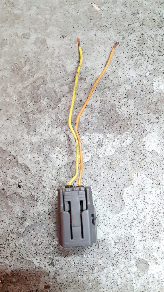

Figure 24 – Plug 30 – Driver Side Seat Belt Pre-Tensioner
In the manual Plug 30 is labelled as the ‘ABS Located in the Back loom‘, but the image actually shows the Drivers side Pre-Tensioner Seat Belt Plug.
Figure 28 – Plug 36 – Fuel Pot
In the manual Plug 36 is not labelled and is actually the charcoal Fuel Pot Connector.
Factory Alarm
Something that is not covered in the manual is the factory alarm. I am guessing that this was not standard with MK2 but was with Mk2.5.

This unit is not needed and can be removed without any adverse issues. Just trace back all the wires and remove them from the multi-joints or connectors. I’m hoping to add this to the manual if my notes are good enough.
The alarm does not have any internal sensors but operates on the basis that if a window is broken and someone gets into the car and then tries to open any doors, boot or bonnet, the alarm will go off. Because none of the door switches remain in the loom, the alarm becomes completely pointless. So it can be fully removed, saving a lot of wiring and a large box which is great.
Keyless Unit
Another thing that is not covered in the manual is the keyless unit. Like the alarm, I am guessing that this was not standard with MK2 but was with Mk2.5.

Like the alarm, this unit is completely pointless once you have removed the door release mechanisms and locks. All it does is trigger the central locking. I thought this might be linked to the immobiliser, but it isn’t, so it can be removed completely. I’m hoping to add this to the manual if my notes are good enough.
Approach to Adapting the Harness
Follow the manual carefully, but watch out for the connector differences above. The manual is good and tells you step by step what to remove.
Aim to complete the removal of all the connectors and cables for each of the 5x looms in turn. The manual focuses on the Main Loom and does not cover the smaller looms as much, as there is less to do. But there is still some tidying up and simplification that can be done on the smaller looms.
Be very prepared that the main harness will get a lot messier before it gets better. I found you’re better actually unwrapping everything as you go. So, if you start unwrapping one bit of the loom, you might as well continue until that bit is completely unwrapped, as it will all need to come off anyway. It gives you much better visibility and speeds up tracing wires back down the loom. Here are a few photos of the process.


Keep Removed Wires
A top tip from me is to keep as much of the removed wire as possible in little bundles. You will find you will need to extend some of the wires down the driver’s side of the engine bay, and using the same coloured wire is much better where possible. This is how much I removed in total.

Insulating Exposed Wires
Once you have stripped out everything you need, then go back and make sure you have insulated all of the multi joints and that there are no bare wires. I bought some 50mm wide black insulation tape from Amazon. This is brilliant stuff! Following the same approach as Mazda for wrapping the multi-joints. You simply get a bit of the 50mm wide tape and lay the joint on it to one side. Wrap it back in itself and wrap the remainder round and round. This works on both single joints as per below or more complex multi joints. I generally used heat shrink and additional tape for good measure in most areas, although probably overkill.

Mk1 Alternator Wiring Adaption
The alternator on my donor vehicle was dead when I took the donor car apart. It has ceased up and there were a couple of large cracks in the casing. A replacement one was definitely needed! The Mk2/2.5 alternator is voltage regulated by the ECU. Whereas the Mk1 alternator has the voltage regulation built into the alternator itself. I had read that if you want to go turbo later and use an aftermarket ECU, it is easiest to get a self regulating alternator so you don’t have to mess around with programming the regulation from the ECU.
So after a bit of research I took the plunge and bought a WAI Mk1 1.8 alternator from BOFI. This also worked out cheaper than the WAI Mk2.5 direct replacement alternator.
To make this self regulating alternator work, the wiring harness need to be modified to stop the ECU from trying to regulate the alternator. I found this great YouTube video with exactly what needs to be done. So all of the credit of wiring diagrams below and approach goes to Fast Rust as the video creator. I ave just taken this guidance and applied it the stripped out MK Indy harness. This modification is made even easier and neater when you have wiring harness out of the car!
Wiring Diagrams
The following diagrams are taken as screen shots from the YouTube video which show the standard Mk2/2.5 wiring diagram and the link to the ECU.
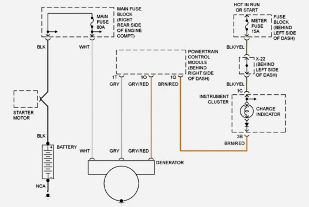
Below is the change you need to make. I have added the ‘AC Fuse‘ comment as I wired in the 12v switched live in the AC fuse circuit which is no longer required for the MK Indy. So you can use the fuse and wiring to the standard fuse box.

Wiring Changes
You can see below the simple joining of Brown/ Red and Grey. Then you can also see the Grey/ Red linking into the fuse box AC Fuse which is the pink wire link. Then the removal of the wires from the ECU connectors. Don’t forget to flick up the catch on the top of the ECU connector before trying to remove the connector.


Tidying up Loom
Once you have all of the exposed wire insulated, you can then start to tidy up the loom, ready for a test fit into the car.
To tidy up the loom, I started to group the wires into natural sections and put small amounts of loom tape around them to hold them in place. Most of the smaller looms are straightforward to get into a sensible shape with some loom tape, and the natural flow of the smaller looms is actually a really good start for installing into the car.


The main challenge is the Main Loom, where the routing is completely different to the standard MX-5 routing. You want all the cables to go down the driver’s side of the engine bay by the inlet manifold to avoid the exhaust side completely. On the standard MX-5, the looms run down both sides of the car due to more room being available.
So, to help with getting the loom into the right place, I created a template of the panel under the scuttle, where most of the loom will go, and then stuck it into my temporary table over the car like this:

This provided a great guide to help shape the wiring loom and group the cables to allow them to pass through the hole in the tray. This definitively made the fitting it to the car later on much easier. The space for everything on the aluminium tray is quite tight. So, the more you can do off the car to get things in the right place, the better.
End Result
You should end up with 5x cleaned up looms with all the cable wrap removed and ready to start laying in the car. This was what mine looked like at the end of this stage. Note: the images below still show the security alarm which I then deleted later once the loom was mainly installed and I realised it wasn’t needed. See the ‘Factory Alarm‘ above.


Summary of Build Costs and Hours
Here is a summary of the costs and person hours (total number of hours for every person that has helped) for the build so far. This should hopefully help others with the planning of their builds, by providing cost and time actually incurred for this build. A more detailed breakdown of all the costs and hours worked on the build to date can be viewed here.
| Person Hours Worked This Post | |
|---|---|
| Strip Out and Adaption of MX-5 Wiring Loom | 26 hrs |
| Car Build Costs This Post | |
|---|---|
| Wire Loom Tape 20m | £10 |
| Black Electrical Tape 50mm x 33M | £7 |
| Totals | This Post | To Date | All Posts |
|---|---|---|---|
| Person Hours Worked | 26 hrs | 445 hrs | 500 hrs |
| Car Build | £17 | £13,394 | £13,956 |
| Tools / Consumables | £0 | £470 | £470 |
| Total Cost | £17 | £13,864 | £14,426 |
