
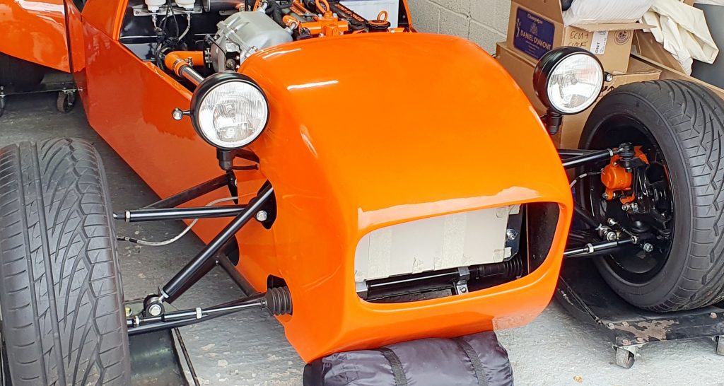
After fitting the wiring loom it was now time to complete the MK Indy Lights install on the vehicle.
Headlights
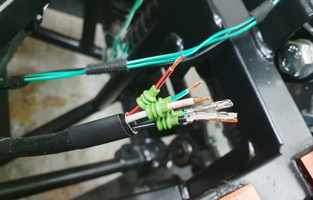
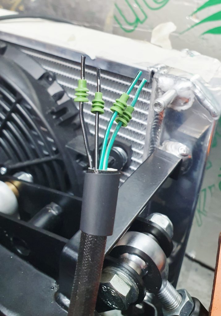
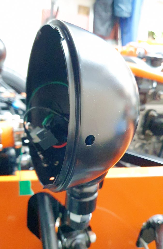
This is one of the first differences with the Mk2.5 in the wiring; there are a couple of wiring colour differences on this part of the loom. Also, MK do something a bit weird with the wiring with no explanation as to why, which caused me confusion until I worked it out. So to save you going through the same head scratching, I’ll explain the weirdness.
Headlight Wiring Logic
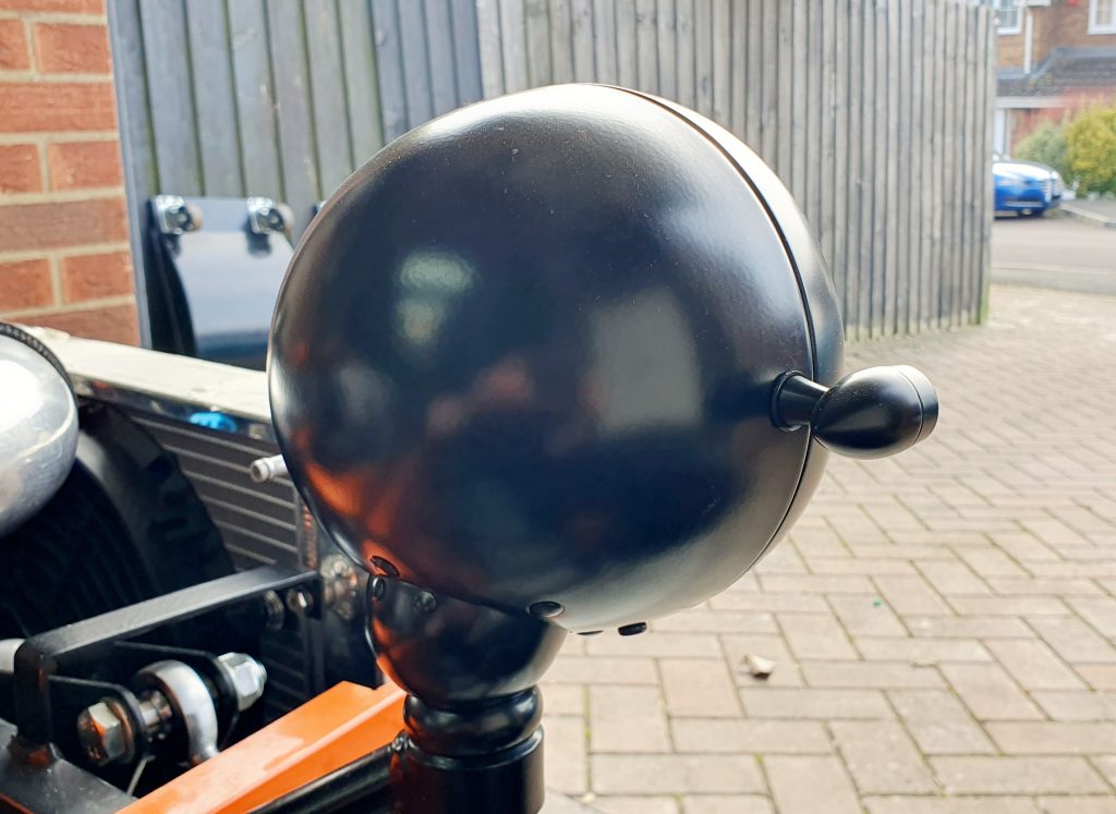
The standard IVA-compliant 7″ Halogen Headlights have a standard earth (black) which is earthed to the headlight case, and the lights are switched on the positive feed. So normally, the black headlight earth would go to the chassis and then apply 12v to the positive wire for each of the bulbs, and they will light up, simple.
The problem is that this is not how the Mazda MX-5 lighting circuit operates. The MX-5 headlight, and particularly the high beams, are switched on the negative. So they have a permanent live feed to the positive on the headlights, and the headlight switch on the MX-5 stalk switches the light to the ground. This makes a difference in how you have to wire up the headlights.
I had not realised that subtly and thought that I knew better and could reduce the number of earth’s being run from the lights compared to what MK said in the manual. Sometimes a bit of knowledge is more dangerous than no knowledge at all! If I had just followed the manual, I would have been OK – except for the colour difference below. But no, I rewired it how I thought would be better, then I wondered why I blew a fuse the first time I tried the lights!
Essentially, what MK do is rewire the headlight so that there is a separate circuit for the side lights by adding a new earth wire, which also earths the headlight case. Then they use the remaining headlight circuit in reverse. So they use the earth, which joins both the main beam and high beam as the live feed instead of the earth. Then use the 2 original live feeds in the headlight to switch to ground using the standard MX-5 circuit.
So the moral of the story is simply follow the MK instructions for rewiring the headlight, but take into account the change in wire colours below for the Mk2.5.
Mk2.5 Wiring Differences
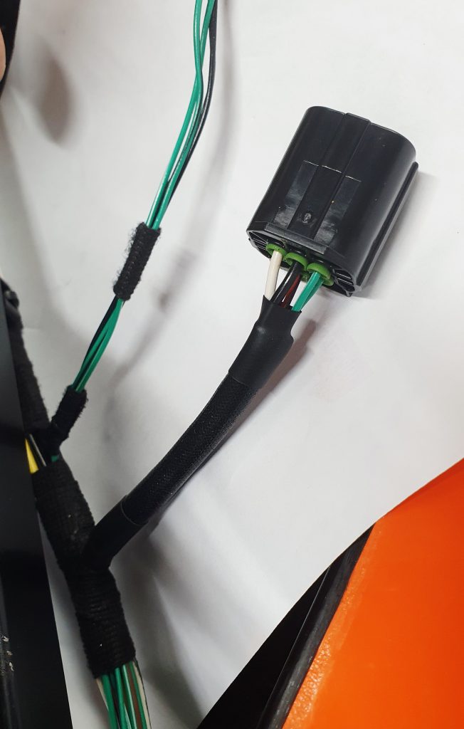
The following table shows the Mk2 vs Mk2.5 wiring colours for the standard IVA-compliant 7″ Halogen Headlights for the MK Indy lights install. The only difference is the headlight +ve wire colour.
O/S Headlight
| Pin # CH001 | Mazda Mk2 | Mazda Mk2.5 | Headlight Loom | Use |
| 4 | White | White | Blue/ White | Headlight High Beam – ve |
| 3 | Red | Black | Blue/ Red | Headlight – ve |
| 5 | Green | Green | Black | headlight +ve |
| 2 | Red/ Black | Red/ Black | Red | sidelight +ve |
| 1 | Black | Black | Black/ White | Sidelight and Indicator – ve |
| 6 | Green/ White | Green/ White | Indicator +ve |
N/S Headlight
| Pin # CH007 | Mazda Mk2 | Mazda Mk2.5 | Headlight Loom | Use |
| 4 | White | White | Blue/ White | Headlight High Beam – ve |
| 3 | Red | Black | Blue/ Red | Headlight – ve |
| 5 | Green | Green | Black | headlight +ve |
| 2 | Red/ Black | Red/ Black | Red | sidelight +ve |
| 1 | Black | Black | Black/ White | Sidelight and Indicator – ve |
| 6 | Green/ White | Green/ White | Indicator +ve |
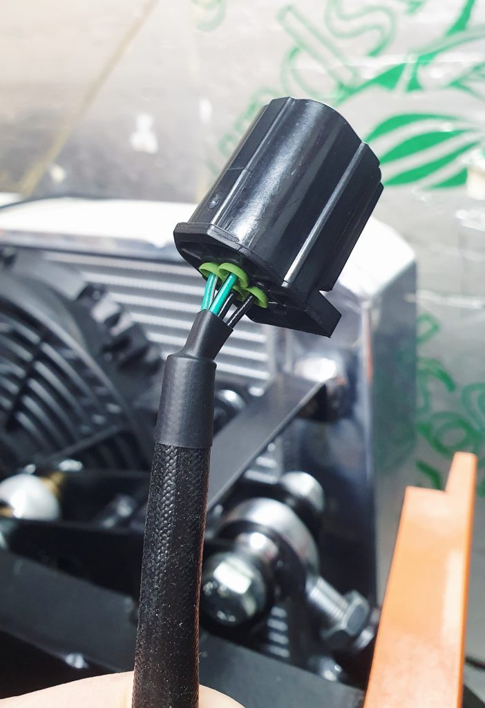
Once I managed to get these wired up correctly, I moved on to the indicators.
Front Indicators
I really don’t like the very long stalks off the nose cone for the front indicators, as suggested by the manual. This is needed to meet the requirement for the indicator, which has to be no more than 400mm from the outside edge of the vehicle. Having indicators flapping around doesn’t do it for me, and the idea of doing it only for IVA then shortening them after also doesn’t work for me either. In my view, the whole point of the IVA regulations is to make sure that the indicators are visible to other drivers.
So, I looked around for options, and this is where I have gone a bit off piste compared to the manual and the general guidance. The issue is getting the indicators either far enough forward or high enough over the wheels and arches to meet the visibility requirements. A reminder of the IVA requirements below.
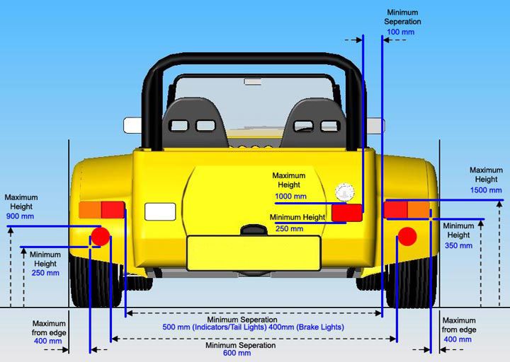
IVA Requirements for Lights
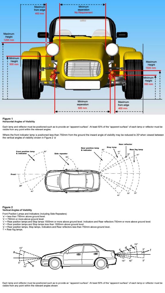
Key elements for indicators for the MK Indy are:
- No more than 400mm from the outside edge.
- Min height 350mm.
- Max height 750mm.
- Min separation 500mm.
- Outside angle 80deg.
- Inside angle 20deg (as long as the indicator is lower than 750mm, which is the case for MK Indy).
- Upper angle 15deg.
- Downwards angle 5deg (as long as the indicator is lower than 750mm, which is the case for MK Indy).
I had seen on the Caterhams, as below, that they position them under the headlight, but the headlights are further forward, so this works with a small extension forward of the indicator.

The MK Indy headlights sit a bit further back, so the indicator extensions would have to be quite long if you mounted them under the headlight on the version of the chassis that I have. MK have since changed the headlight mount to a bolt-on, which puts the indicators under the headlight.
So, I came up with an idea that hopefully will work, be a neat permanent solution and be IVA compliant. Fingers crossed.
Front Indicator Solution
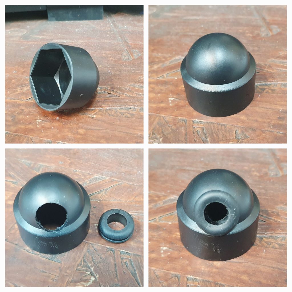
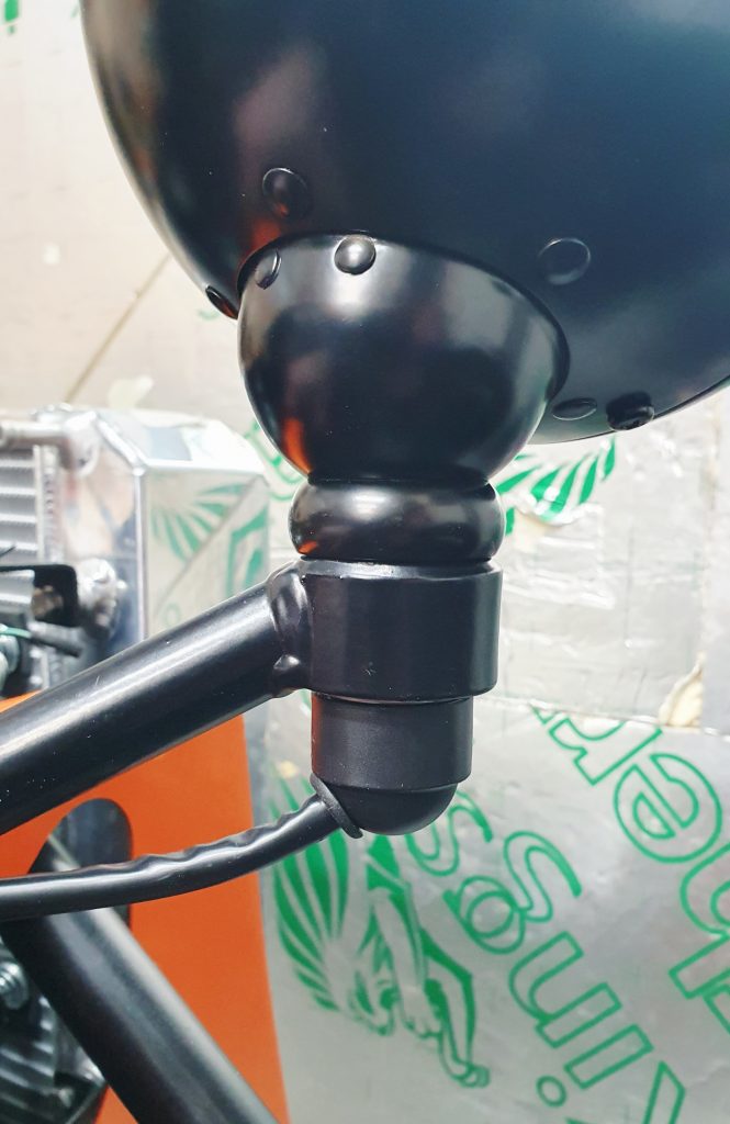
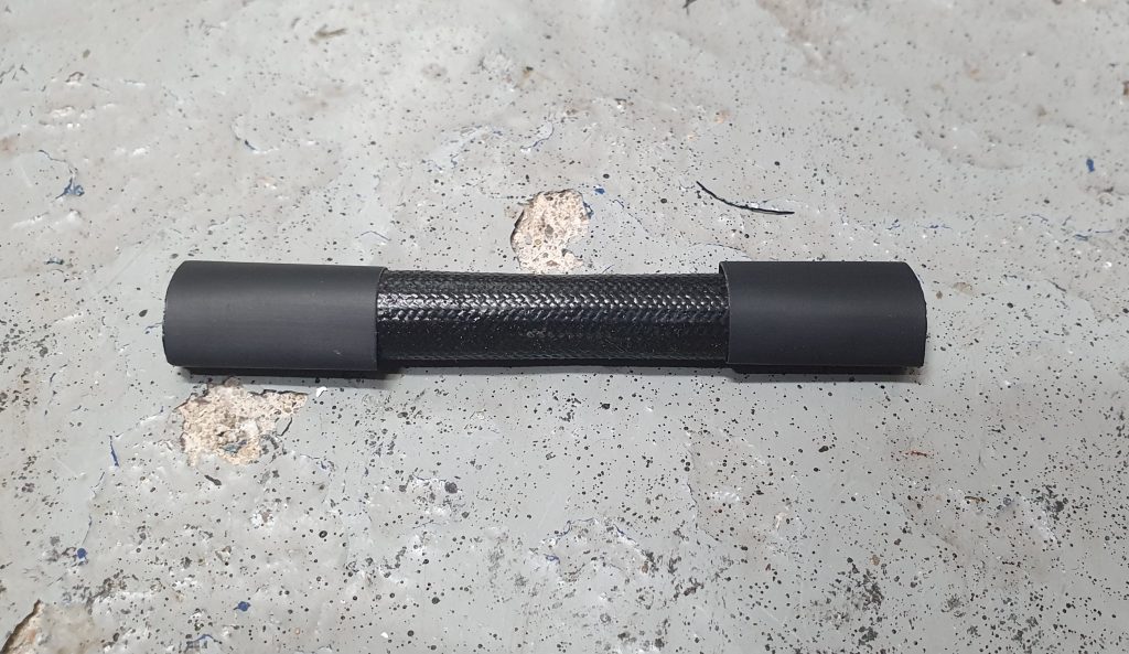
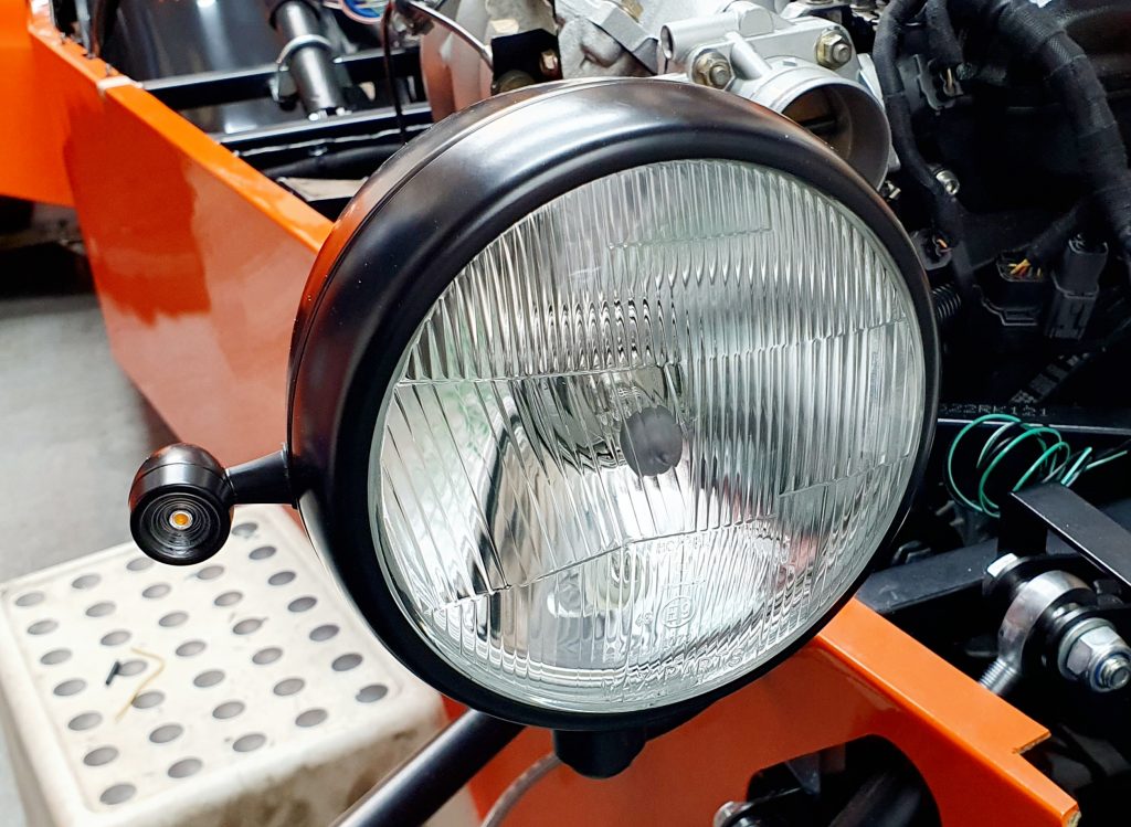
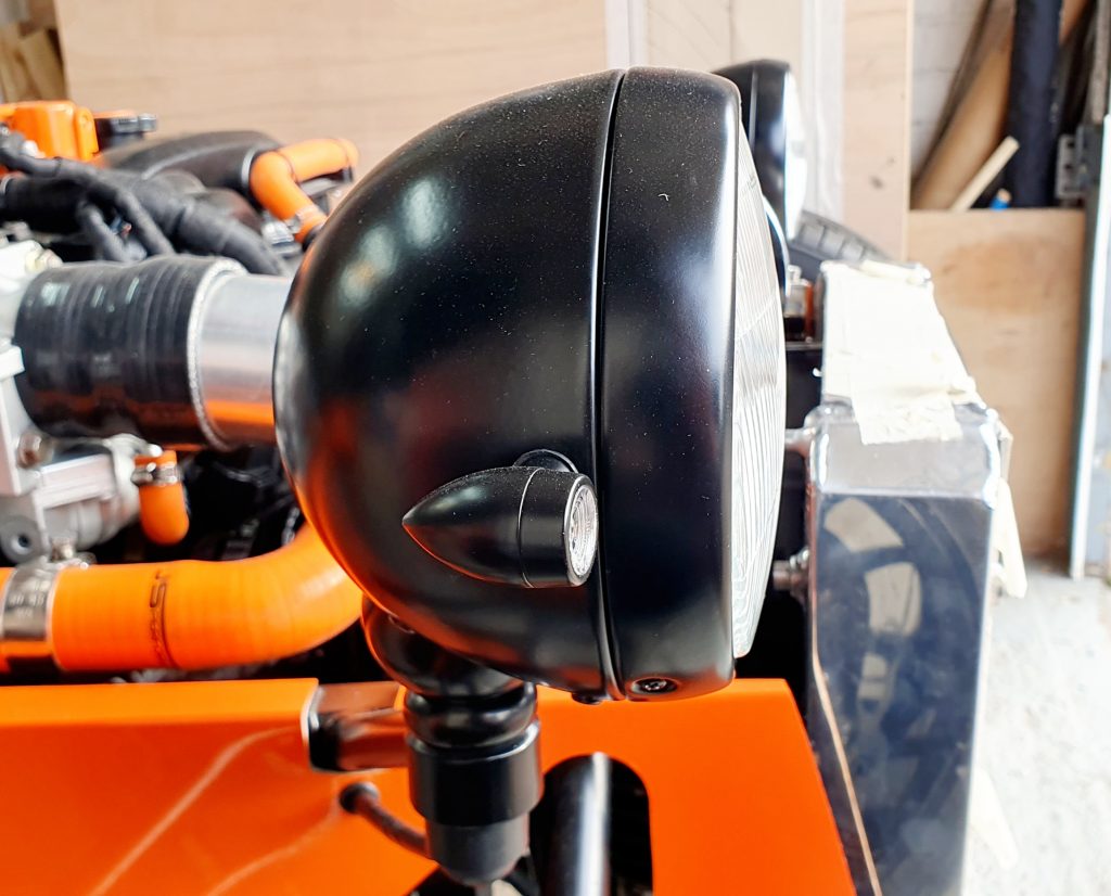
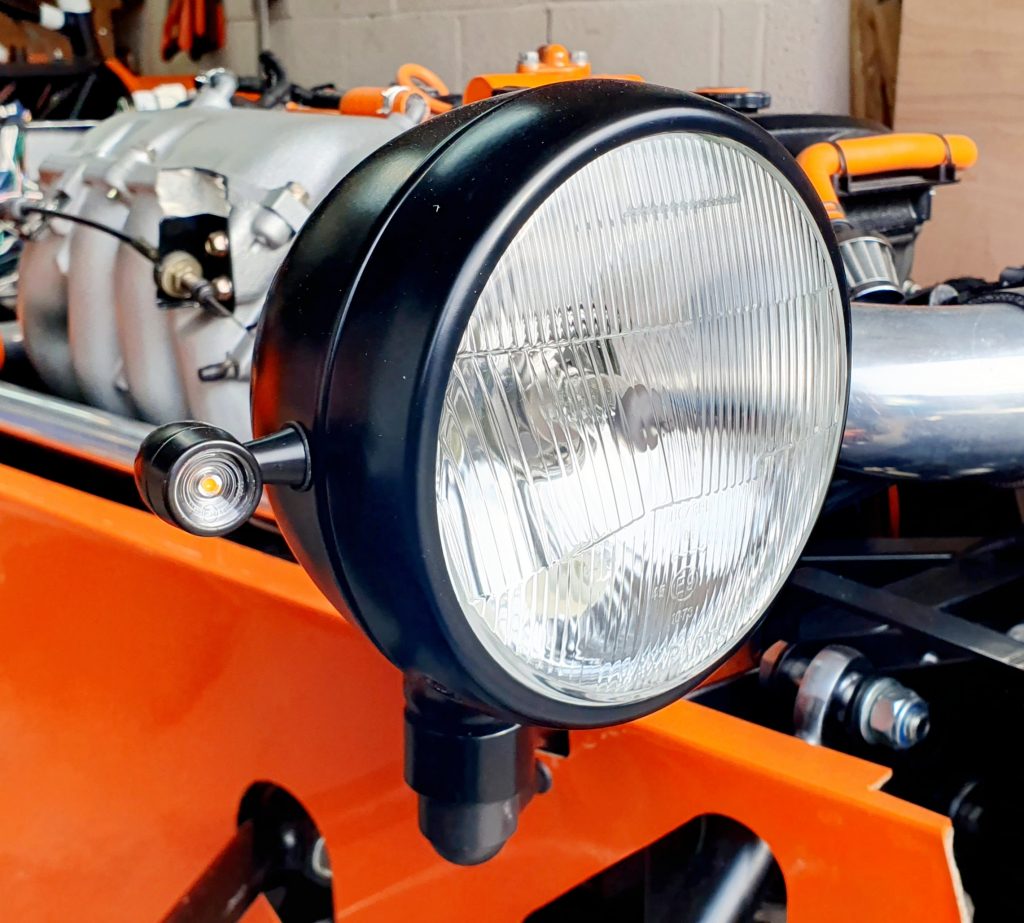
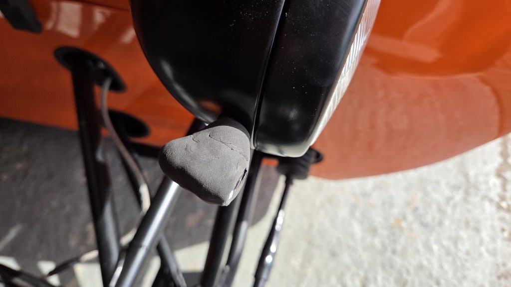
After some careful measurements with a string taped to the side of the headlight to measure angles, I worked out that an indicator light fixed to the side of the headlight case would work. I found some neat motorcycle indicators on Amazon that are e-marked that matched the style of the headlights. The only thing they don’t quite meet is the radius specifications for sharp edges, so I will need to add a bit of trim or similar for IVA.
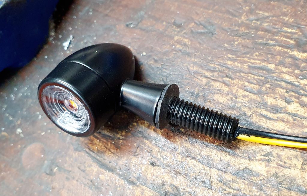
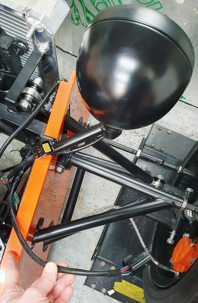
The beauty of these is that I then fitted them directly to the side of the headlight casing with an 8mm hole, and I could therefore run the cabling down the same route as the other headlight cables, keeping it tidy. I’m pleased with the result.

The only issue that remained was that all the LED indicators were hyper flashing. This is where the indicator flashes way too fast due to the lower resistance of the LED lights. Luckily, I found a simple, cheap way to fix this, which I have detailed in another blog, as it is generic to all MX-5s, which can be found here.
For IVA I also added some air-dry foam to the outside of the indicator casing to make sure it fully meets the minimum radius for edges of 2.5mm. Not a pretty solution, but it should be good enough.
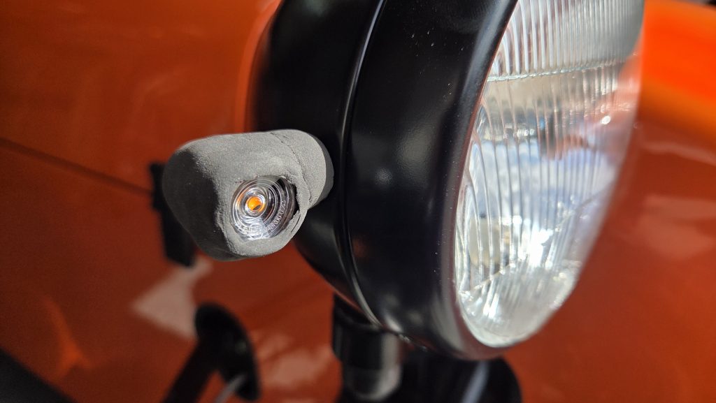
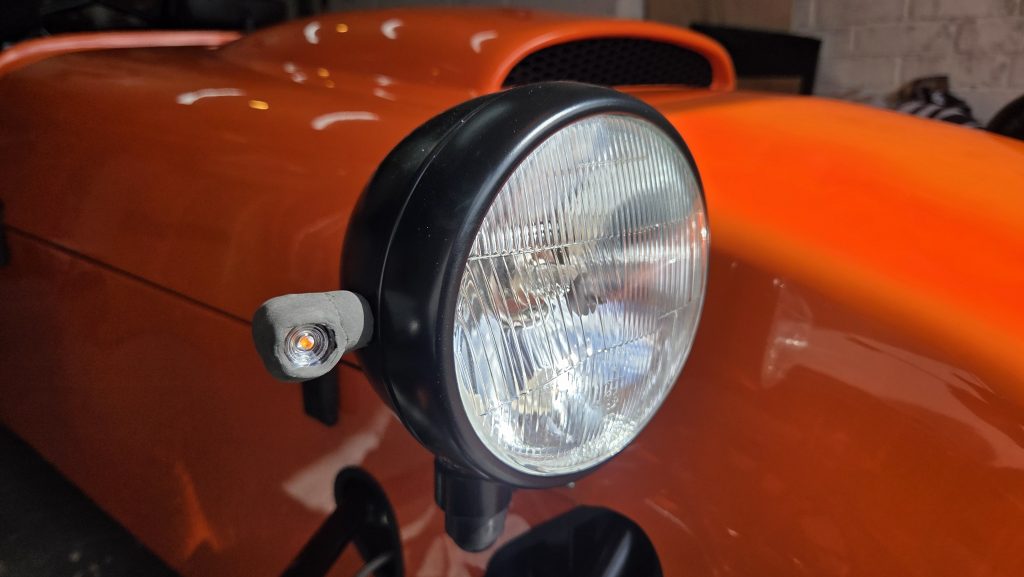
UPDATE Post-IVA – This solution passed with flying colours and met all of the visibility requirements as well as the sharp edge requirements!
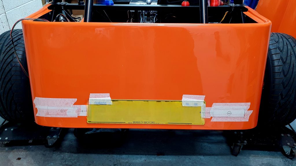
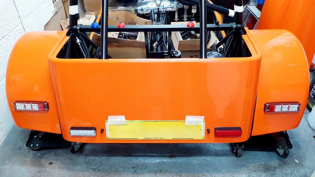
Rear Lights
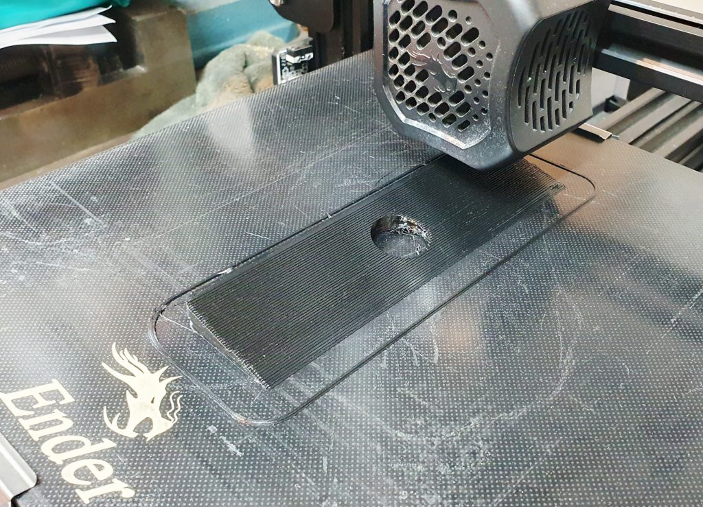
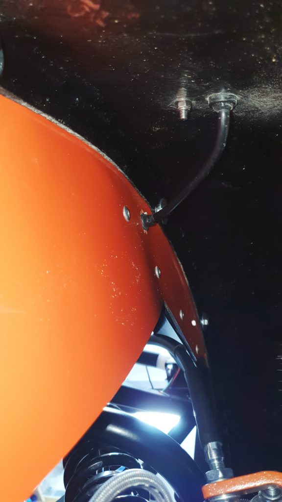
For the rear lights, I went for the standard LED light setup for the MK Indy with the separate reverse and fog lights. I used a 3D printed wedge to mount the fog light and reverse vertically. The fog needs to be vertical for the IVA. Rich from the MK Indy user community kindly provided the CAD file he created for the light wedge, which I just printed on my own 3D printer in black PETG. It worked a treat, cheers Rich!
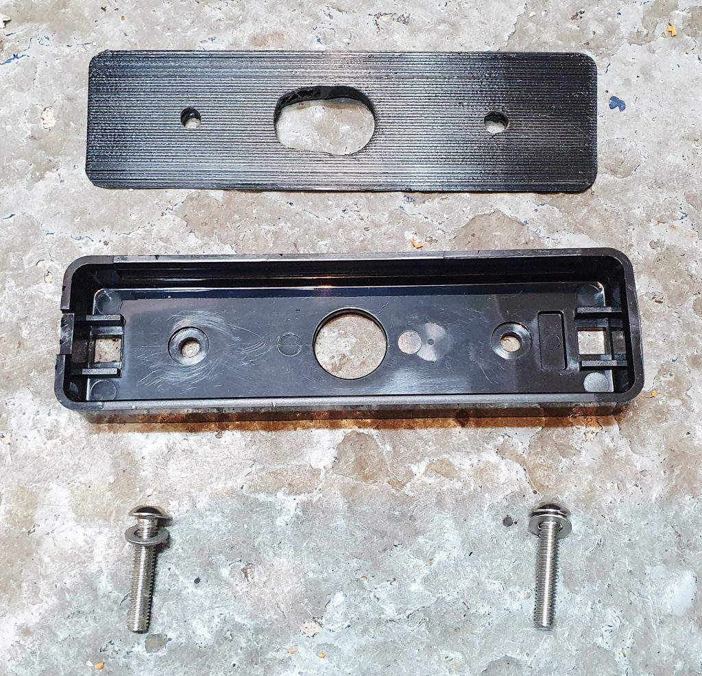
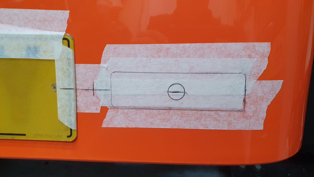
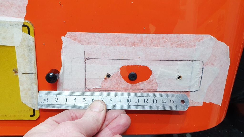
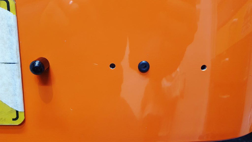
For the number plate lights, I decided to use some small button LED lights designed for motorcycles. I designed a small spacer in CAD and printed it in black PETG to space the lights off the body to provide better coverage across the number plate.


Then I marked everything out on masking tape before committing to the cutting – measure multiple times, cut once. I also looked at several photos and took a bit of judgment as to where I thought the lights looked best. Also a double-check that the final locations chosen met the IVA Requirements below.
Here aare some of the photos of the final fitment of the rear lights.
Hazard Light Switch
I was going to use the original MX-5 switch for the hazard light switch, but then I realised I forgot to remove the surround for the switch from the dash before I sold it. So either buy a new surround, use some u-trim or use it as an excuse to buy a neater switch. I bought a new switch.

My intent was to wire it up so that when the switch was on, it would flash with the lights. I thought this would be simple to set up, looking at the wiring diagram and thought I had it working. The switch triggered the hazards, then using the right-hand indicator to power the light on the switch, simple. The only problem was that the hazard switch light still lit up when you indicated right normally. I thought it would only work when the switch was on, but this was not the case.
No matter what I did, I couldn’t configure it to work in the way I wanted. So, I ended up giving up and just not using the light on the switch. This is not really a problem as the MX-5 switch didn’t have a light and the ‘telltale‘ IVA indication is still provided on the lights on the dash, so not a big issue.
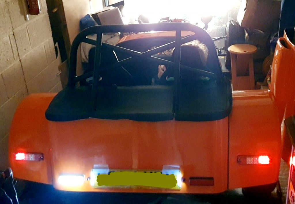
Final Testing
Once everything was complete, I did a final check of all the MK Indy lights install to make sure that all the lights worked as they should. This was a satisfying moment and made all the hours spent sorting out wiring worth it! The only lights I couldn’t test were the brake lights, as I didn’t have brake fluid in yet.
Summary of Build Costs and Hours
Here is a summary of the costs and person hours (total number of hours for every person that has helped) for the build so far. This should hopefully help others with the planning of their builds, by providing cost and time actually incurred for this build. A more detailed breakdown of all the costs and hours worked on the build to date can be viewed here.
| Person Hours Worked This Post | |
|---|---|
| Installation of Front Lights | 4 hrs |
| Installaiton of Rear Lights | 5 hrs |
| Car Build Costs This Post | |
|---|---|
| Oxford Halo Bolt Number Plate LED Lights | £17 |
| Motorbike Indicators LED Mini Bullet | £15 |
| ETOPARS Car Hazard Light Switch | £10 |
| Totals | This Post | To Date | All Posts |
|---|---|---|---|
| Person Hours Worked | 9 hrs | 486 hrs | 500 hrs |
| Car Build | £42 | £13,570 | £13,956 |
| Tools / Consumables | £0 | £470 | £470 |
| Total Cost | £42 | £14,040 | £14,426 |
